|
|
|||
|
|
|||
|
|
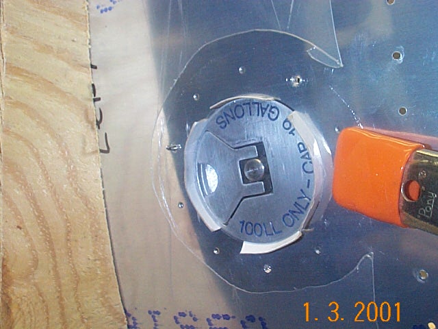
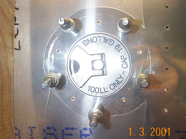
After drilling the tank skins to the ribs then dimpling and deburring the skins, it's time to drill the other components to the skins in preparation for Proseal. The fuel filler flange and fuel drain are shown here. I used some thin cardboard to space the fuel cap evenly. This wasn't necessary as the picture of tank #2 shows. Just slip the filler through the hole and back drill through the skin holes. The filler is cone shaped and will center itself.
|
||
|
I lost the main picture so all you get is the thumbnail---sorry |
After drilling the fuel filler to the skin, I countersunk the filler for attachment to the skin. |
||
|
|
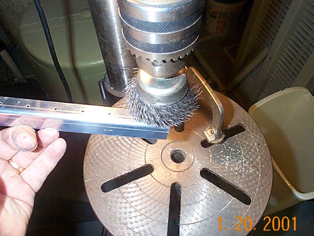
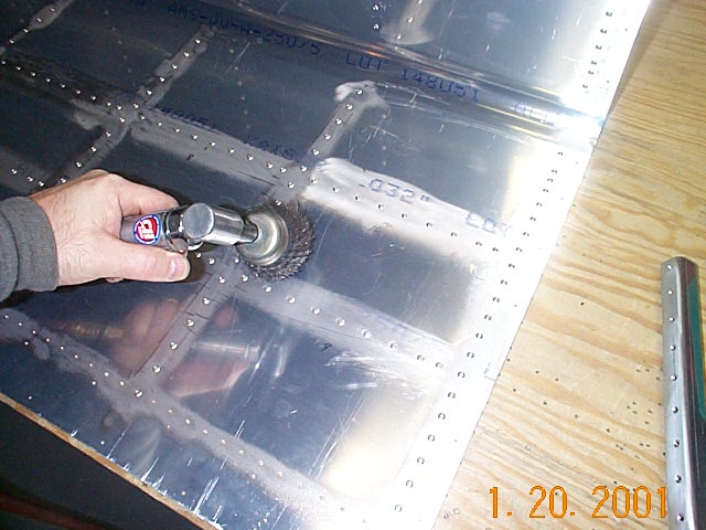
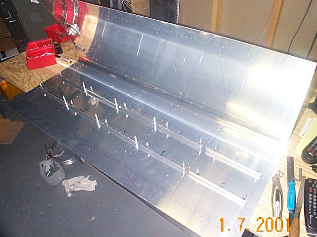
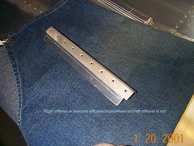
The bottom of the fuel tanks are fitted with stiffeners to help support the tanks when they are full of fuel and also help keep the fuel from sloshing around too much. The stiffeners are cut to length. Be advised, one of the end bays uses a longer stiffener than the others so don't try to cut them all the same length. After making the stiffeners and drilling them to the skins, I used a wire brush mounted in the drill press to scuff the stiffeners. I also used this same wire brush in a die grinder to scuff up the skins. Note: I tried using a handheld wire brush but, and trust me on this, the wire wheel in a drill or grinder is a lot easier.
|
||
|
|
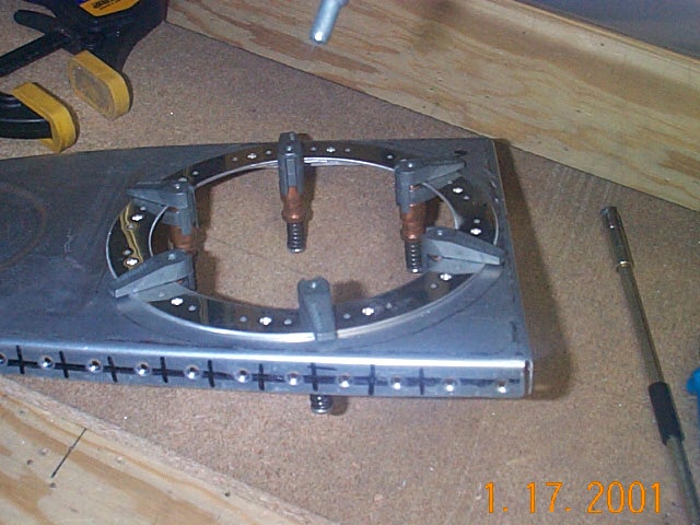
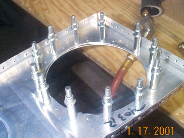
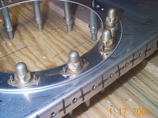
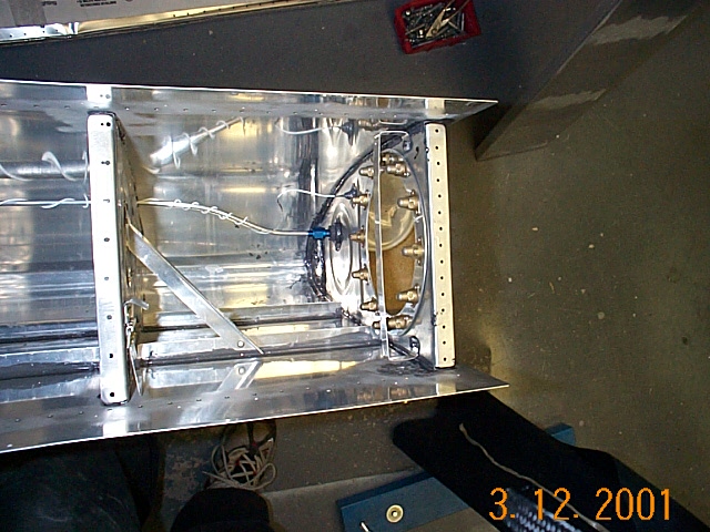
Next I fabricated the tank access cover and
reinforcement plates. Care must be taken to ensure the access cover plate is orientated properly before drilling. There is a flat side of the cover plate that lines up with the indentation on the rib. Next I installed the nut plates and the reinforcing ring on the inboard rib. If your not careful (like me) you'll just mount the reinforcement plate on the rib without regards to where the nut plates line up and the cover plate will not be right. I use NAS 1473A08 nut plates instead of those supplied in the kit. These nut plates are sealed and should prevent any fuel leaks in this area. At $2/ea. and 12 per side......well, you do the math. |
||
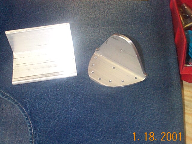 |
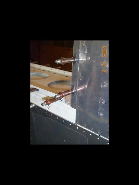
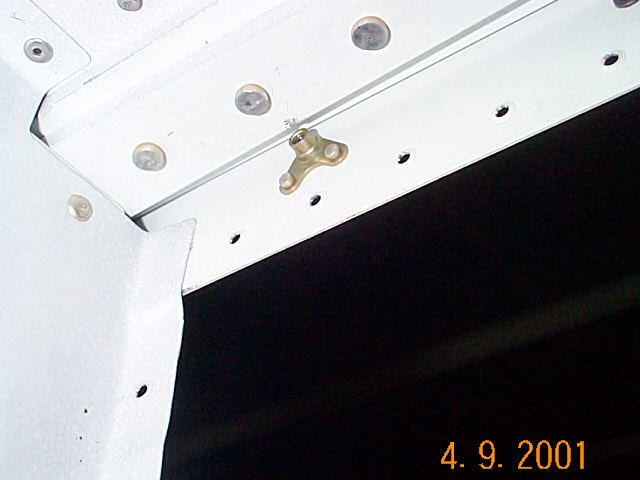
The pictures at the left show the before and after condition of the wing attach bracket that needs to be fabricated. Watch where you drill dem rivet holes! | ||
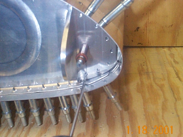 |
The tank attach bracket is positioned next , along with the reinforcement plate on the other side of the rib (not shown), with the rib and drilled in place. | ||
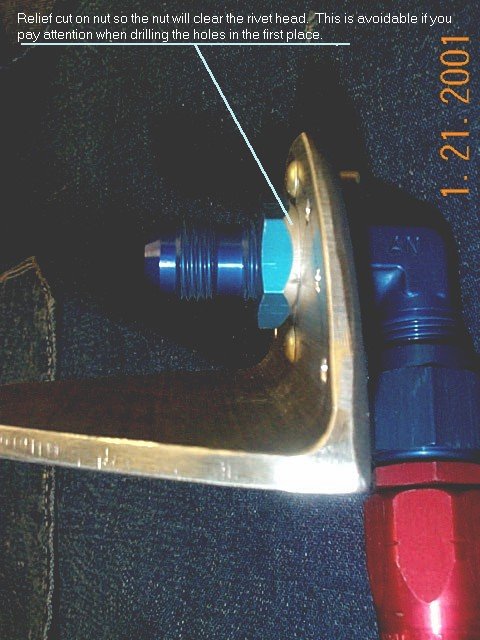 |
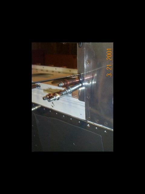
The 9/16" hole for the fuel pickup
fitting is then drilled through the tank attach bracket, rib and
reinforcement plate. I didn't calculate correctly and the nut would
not clear the rivet heads when I tried to tighten the
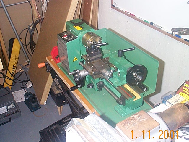
fitting in place. A quick job with my $185 garage sale lathe and there was a nice bevel on the nut so everything works ok. |
||
|
|
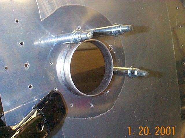
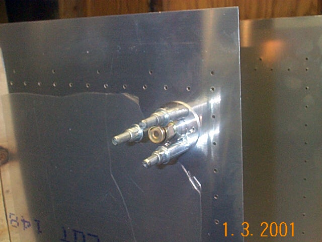
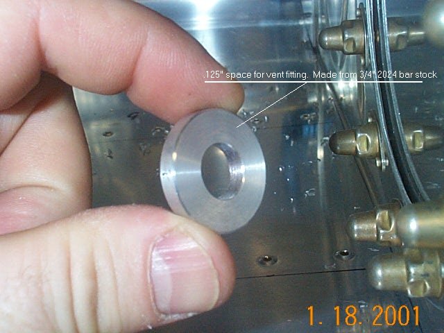
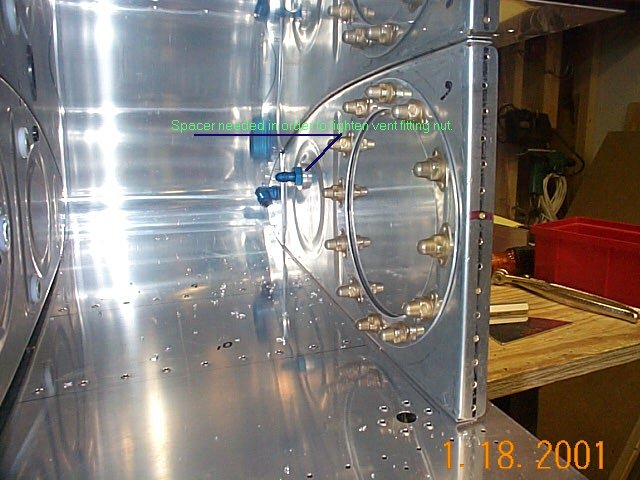
The Orndorff tapes briefly talk about it, but the manual does not. The AN fittings that are used for the vent tube will not lock tight to the rib because the rib is not thick enough. A spacer needs to be fabricated from some scrap aluminum as shown on the pictures. I had some scrap 3/4" round stock sitting in the corner and used the lathe to turn out the spacer you see. The tank vent fitting is next and is pretty straightforward. The positioning is called out on the plans but is not critical. On my second tank, I will position the vent fitting so that it's more of a straight shot for the vent tube as it goes through the ribs. |
||
|
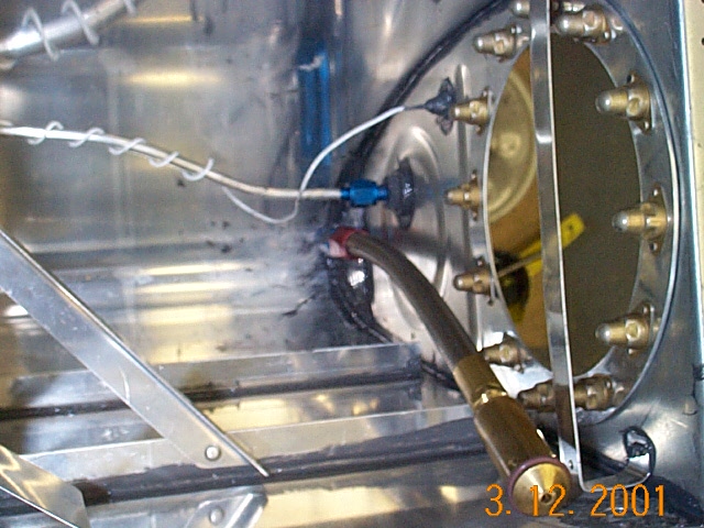
This is the outboard bay showing the fuel filler and vent tube.
Notice I forgot to secure the vent tube to the filler neck. I had to
drill a separate hole to secure the vent tube mounting bracket.
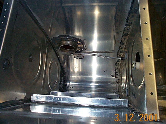
This is the outboard capacitance fuel sender plate. You can see the wire that runs along the vent tube to the next plate mounted two ribs inboard. Here is the second fuel send plate. The wire from the first plate attaches here then goes to the BNC connector mounted on the first inboard rib. Here is the inboard most fuel bay. The fuel pickup is missing in this shot but you can clearly see the vent tube fitting and BNC fitting for the fuel senders. You can also see the guides that keep the flop tube from getting hung up on the access ring nut plates. Here is a bad picture of the same fuel bay but with the flop tube in place.
Here is the completed tank ready for Proseal. |
||
|
Mounting the Tanks |
|||
|
|
|||
|
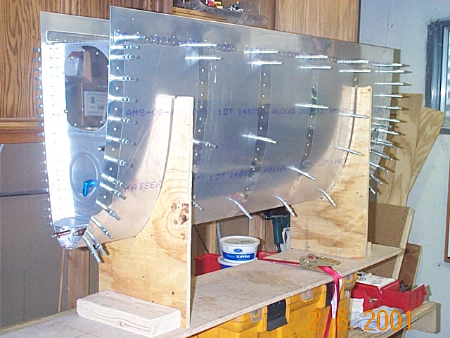
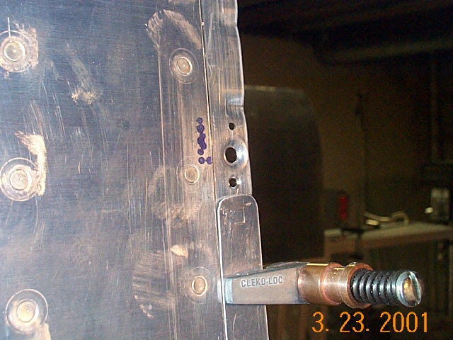
After Prosealing is complete it's time to start mounting the tanks to the spar and leading edge. The first step is to set the tank in place and start fitting and filing and fitting and filing until the tank fits against all the skins just right. One tank took quite a bit of filing and the other very little. Next, while the tank is in place, drill the holes that attach the tank to the Leading Edge and the spar. I drilled these holes with a 330 bit so I could cleco the nut plates on | ||
|
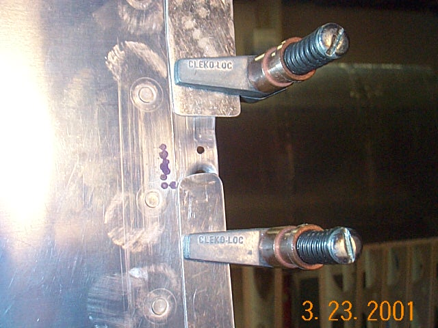
After the nut plate is cleco'd on and positioned properly, I drilled one lug with a #40 drill and held that in place with a cleco. After that the second lug can be drilled. To speed the process, I did each task on all the nut plates before proceeding to the next step in order. | ||
|
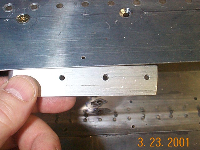
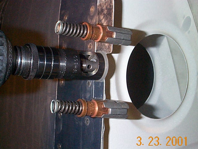
When it came time to counter sink the tank skins I used a piece of aluminum with a #30 hole. This piece is held with a clamp behind the aluminum skin and is a guide for the pilot on the countersink bit. It keeps the countersink bit from walking and making an odd shaped hole. | ||
|
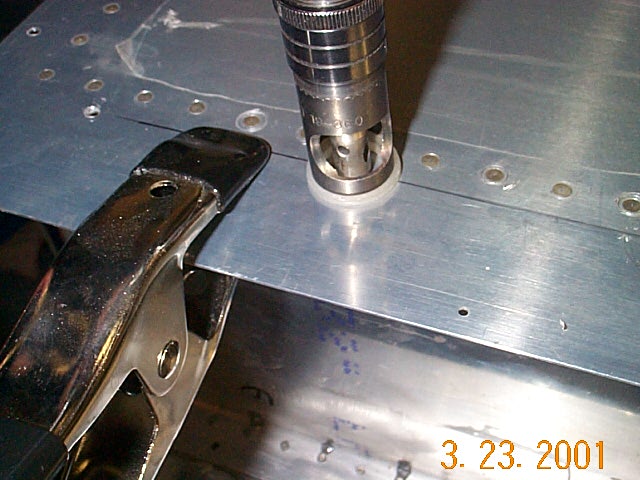
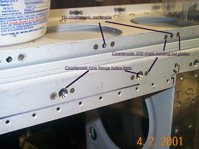
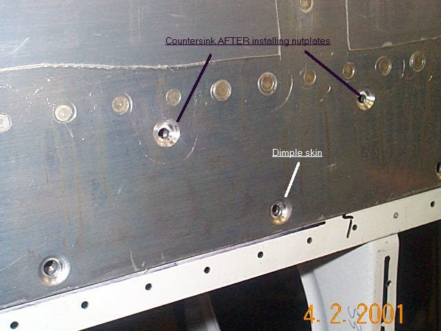
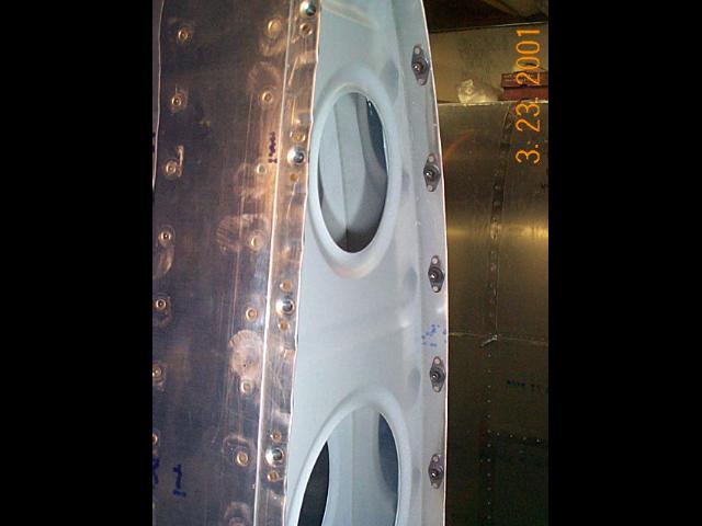
Here are pictures showing what gets countersunk and what gets
dimpled.
In the pictures above, I show a method for countersinking the skins. On the second tank, I installed the nutplates and used the nutplates to hold the pilot of the countersinking bit. I drilled the #19 hole AFTER countersinking. Worked great. |
||
|
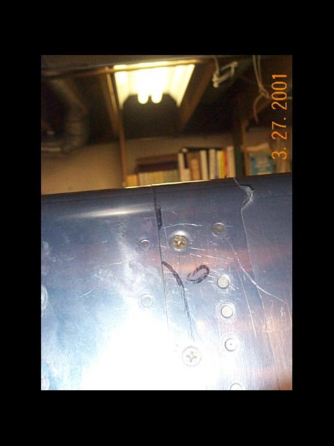
On one of the wings, I had to make some modifications to the hole locations and the holes were drilled to close to the spar strips. In order to get the nut plats to fit so I could rivet them in place, I used this angel nut plates. I had to do this with about 5 nut plates on the bottom side. | ||
|
These three pictures show how I countersunk the Leading Edge skin.
The aluminum strip that connects the LE and the Tanks together is
difficult to countersink because of the step down. I used some side
grips to hold some strips of aluminum so the countersink cage would set
flush.
On the first tank I just used the deburring tool to countersink all the these hole. It wasn't as easy but didn't take much longer. |
||
|
Leading edge nut plates installed. | ||
|
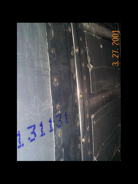
This is the bottom side of the wing showing the joint between the Leading Edge skin and the Tank skin. There is virtually no buckling here at all. The top side is even better. I'm very please with how both tanks turned out here. | ||
|
This picture shows the leading edges joined together. Even though the
skins are different thickness the fit very nicely. I've seen quite a
few tanks where this joint didn't come out very well.
Beth still can't understand why I'm so excited about how these turned out. |
||