Servo
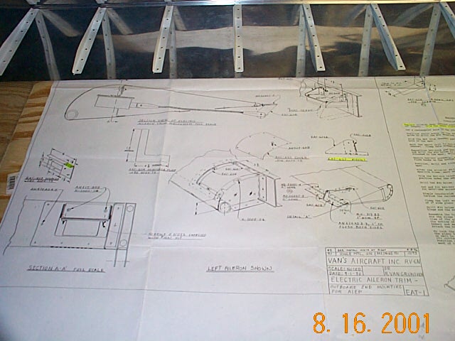
I've decided to use a modified version of the optional electric aileron trim. I will mount the electric servo as depicted in the plans but I don't like the hinged trim tab hanging off the aileron so I'll be designing and building a flush trim tab similar to the elevator trim. I saw something similar on Dick Martins RV-8 and I'll attempt to re create it.

The trim kit comes with a doubler plate to replace one of the A-408 plates. A bracket will be fabricated that will mount the servo to this doubler plate. I drilled 4 holes in the corners and used a Dremel tool with a cutoff wheel cut out the square hole. I then used a pneumatic nibbler to try and clean it up and that was a mistake. Wrong tool for the job and the hole isn't nearly as clean as I'd like. It won't be visible and it's solid so I'll use it.
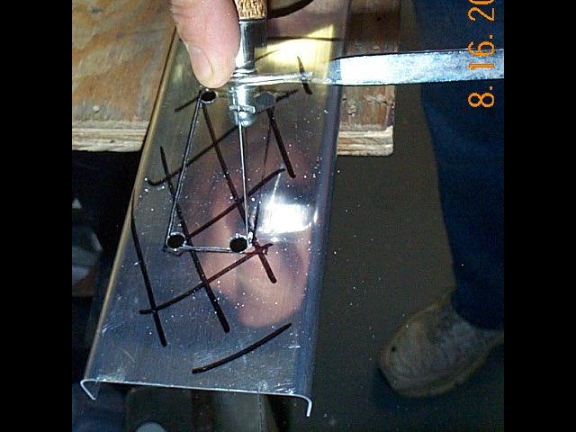
The coping saw is a fast and easy way to cut square holes.
I also had to cut the same size hole in the aileron spar. My friend Paul suggested I use a copping saw for a more precise cut. Considering how slopping the first one was, I gave it a try. Worked like a champ. Just drill 4 holes in the corners and saw away. I could have cut closer to the lines and saved myself a bunch of filing but it turned out very nice
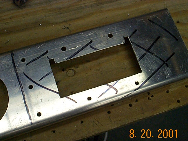
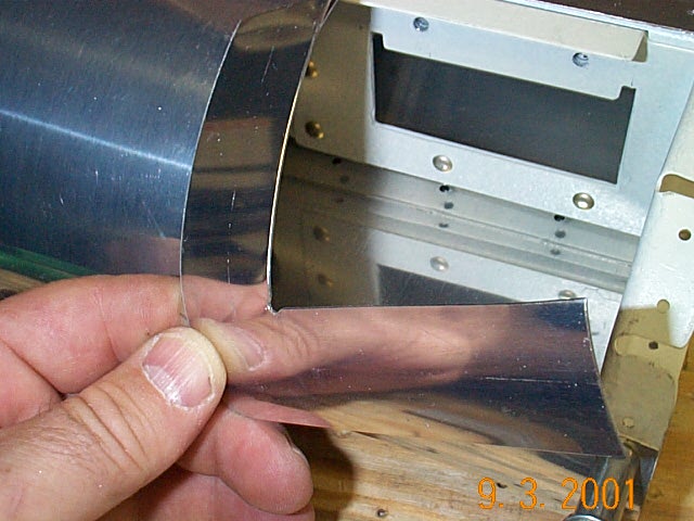
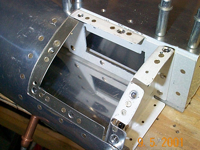
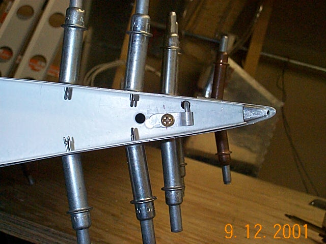
This picture was taken after the doubler plate was mounted then removed
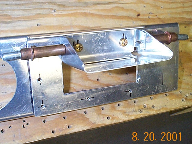
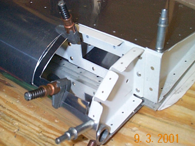
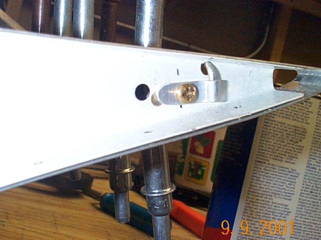
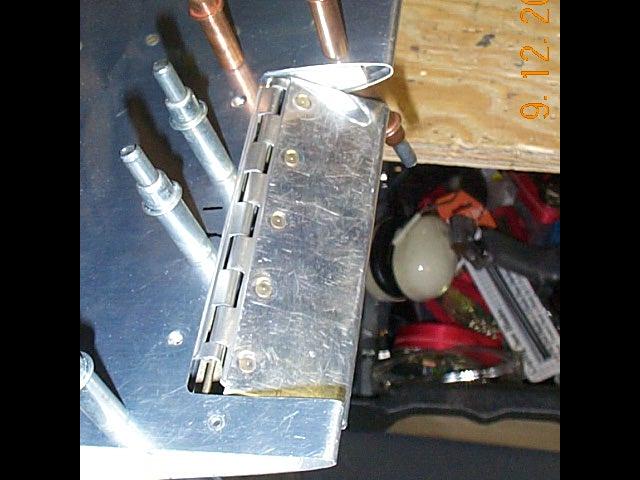
A mounting bracket for the trim servo needs to be fabricated but I forgot to take a picture of the fabrication process. Here is the end result mounted to the aileron spar with nut plates.

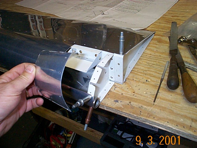
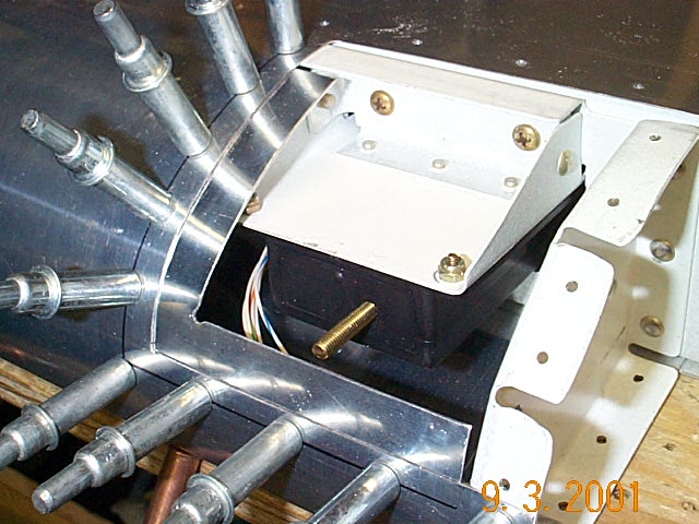
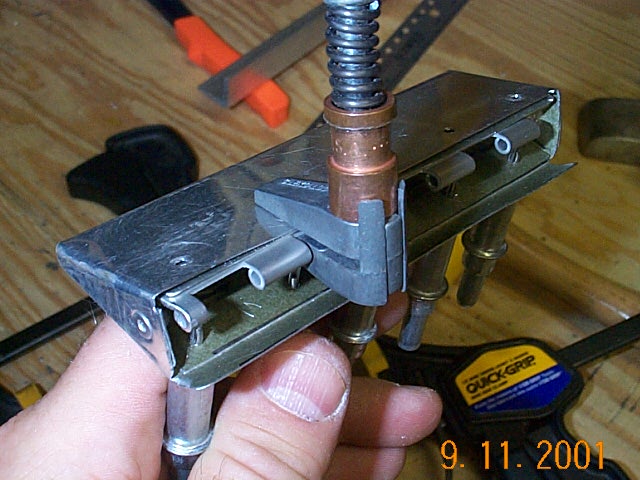
Trim servo mounted in position for fit.
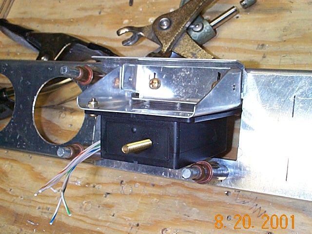
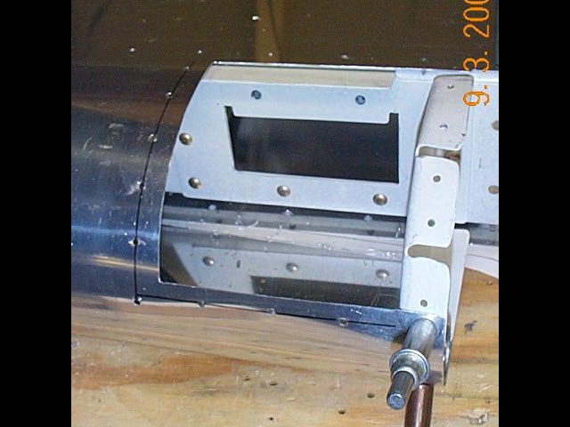
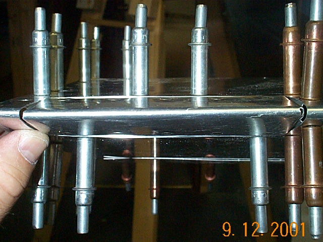
The servo is matched drilled to the mounting bracket and installed on the aileron spar. In these pictures the mounting bracket has not been riveted yet. Everything still needs to be primered.
The trim tab itself will be fabricated after the skin has been drilled to the skeleton. I'll have that process documented in the next couple of weeks
After the skin is riveted and dimpled, it's time to make the access panel to access the servo. This is fabricated on the leading edge of the aileron. I made a mistake that you can see in this photo. I should not have drilled the rib since I will be making a new cover plate. These holes in the rib will cause me problems a little later.

The first step is making a doubler plate for the access panel. Since the leading edge has a nice curve in it I have to curve the double plate to match. I couldn't figure out how to make the curve until I saw a large piece of PVC sitting in the corner. With thoughts of rolling cookie dough and how it sticks to the rolling pin, I made a really cool curved plate. I then cut it to size.
You can see in the left picture how the curves didn't quite match so more rolling took place. Let me warn you, make sure the rolled curve matches aileron curve before riveting.......
In this picture it looks like everything is matched and ready for riveting. There was a little difference in the curves though and because the double plate is thicker than the .016" aileron skin guess which one won when they were riveted together.
The nutplate installation was a little messy give the small area to work in
It's tough to see in the left picture but there is a little flat spot. It won't be noticeable to the air when flying but someone at a fly-in somewhere will probably see it. Remember those extra holes I drilled earlier? They got in the way when installing the nut plates. I removed one of the flanges and replaced it with a home made piece. Works great.
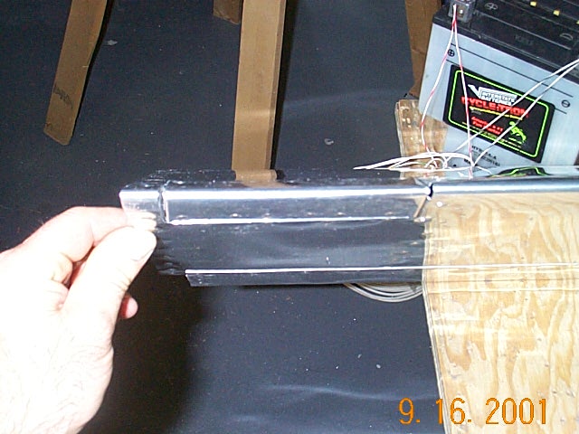
The little rubber grommet is for the wires from the servo that will exit. The wires will then run to the wing rib conduit.
With the cover all rolled, drilled and dimpled everything fits pretty nice and looks good.
Now on to the hard part. Deviating from the plans to make the trim tab itself.

Instead of a hinged tab hanging off the trailing edge of the aileron I decided to build and integral tab ala the elevator trim. The first step is to cut out the material where the trim tab will go. I drilled holes in the corner prior to cutting but then decided I wanted the trim tab a little larger hence the second set of holes.

The Dremel tool does a nice job of cutting the aileron skin.
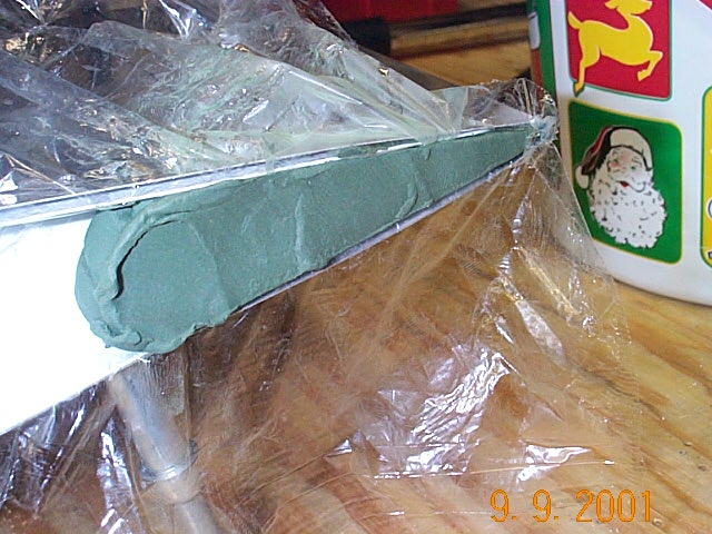
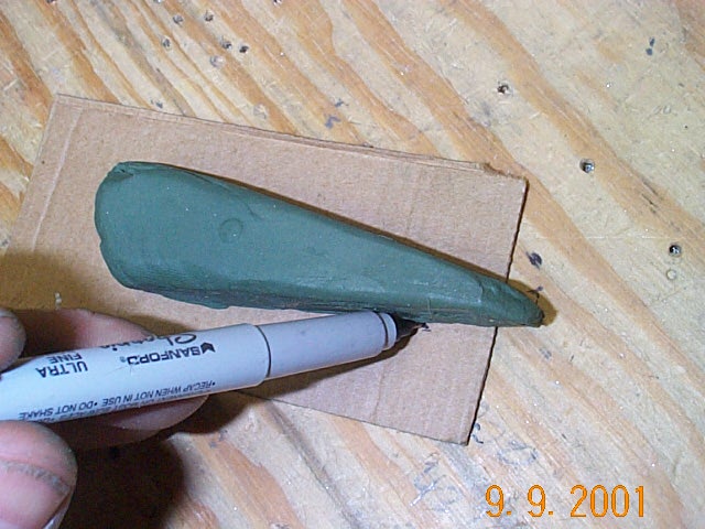
Next I had to make a "riblet" to support the skin next to the stiffeners. The outboard rib will the support the skin on the left side of the trim tab. I used some modeling clay and plastic wrap to make a mold for the shape of the "riblet". I removed the clay and traced the outline on some cardboard to check for fit. I then traced the outline on some aluminum then bent the aluminum to size.
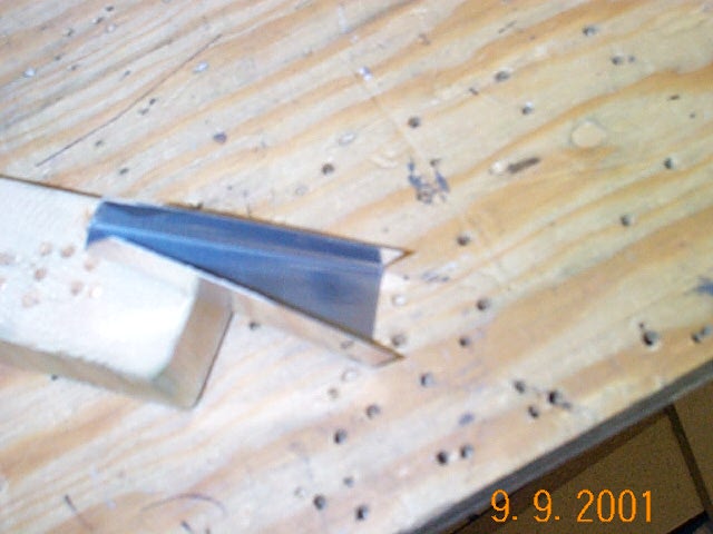
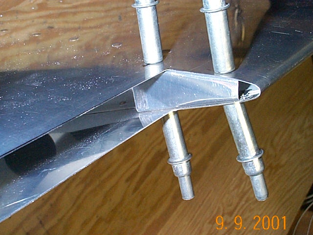
The finished "riblet" (sorry for the picture quality) is shown and then the "riblet" is installed and cleco'd in place.
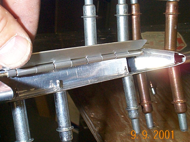
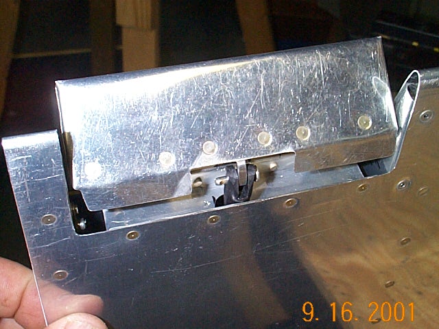
I forgot to take a picture, but I then made a small trim spar out of some extra .016" sheet that can be seen in the picture on the left. I also cut and installed the trim tab hinge and hinge pin locking device at this point.
Nut plate and hinge eyelet work well to secure the trim tab hinge pin.


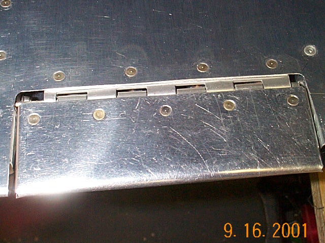
The trailing edge shows that the tab is nice and even with the aileron. Lots of work.