Main Rib Preparation
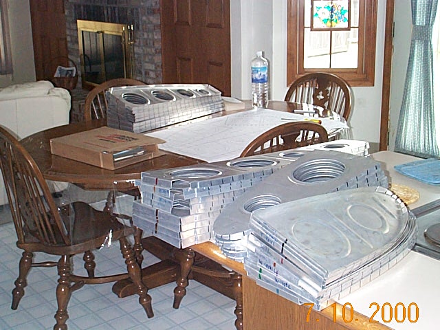
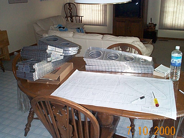
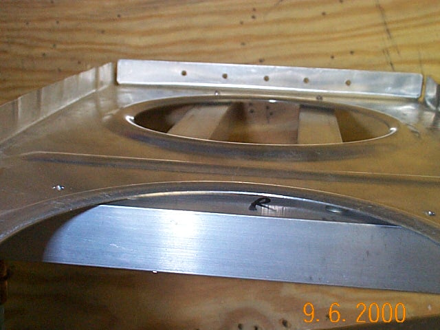
It would have only taken one scratch on the kitchen table to wipe the slate clean on that nice gesture. I got lucky, not a mark.
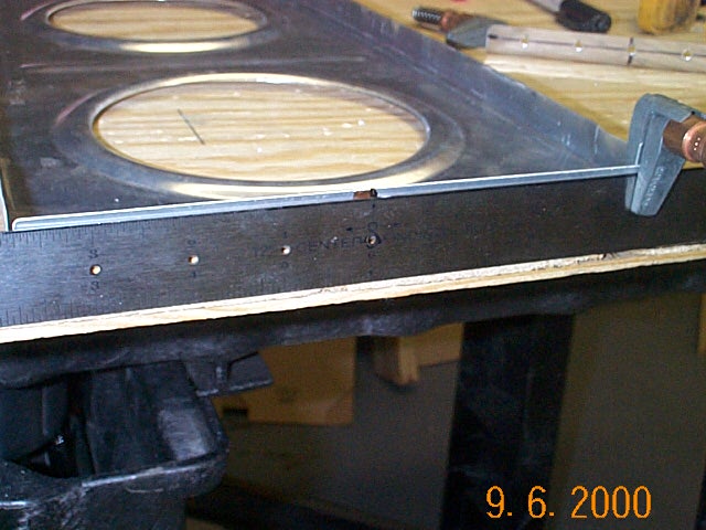
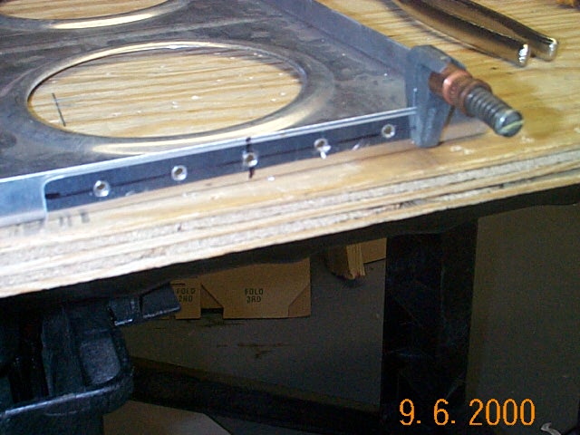
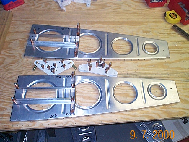
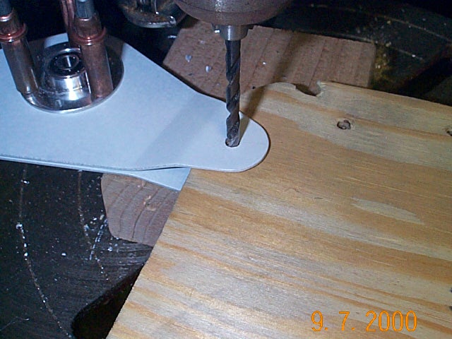
The next step is to make a template out of a piece of stiffener angle. Follow the plans for spacing and you should not have a problem with any of the holes going through the main spar flange strips. Use the template to drill all the main ribs on the end that attaches to the main spar. You'll drill the aft end of the main ribs using another template later.
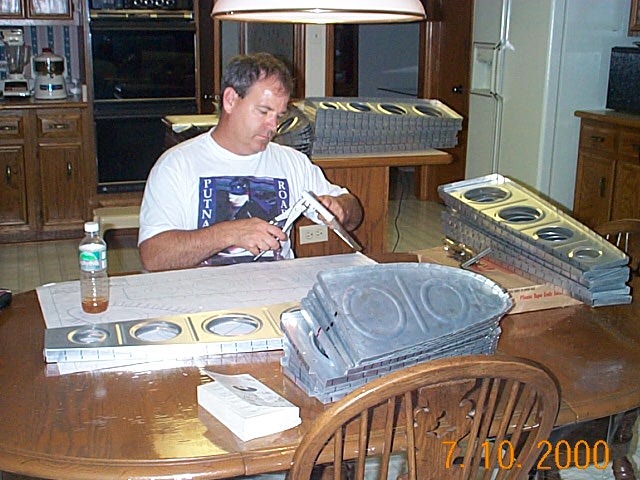
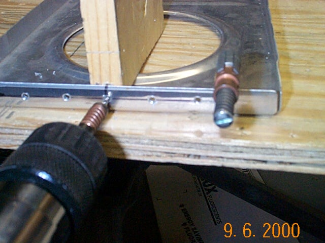
I then clamped the template to the rib flange and lined the center of the rib up with a mark on the template. I used a piece of wood to back up the rib flange while I drilled the holes. I was able to drill all the main ribs (28) in about a half hour.
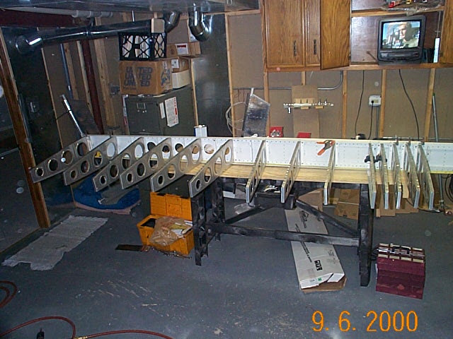
The Orndorff videos and other builder web sites, show the wing skeleton being assembled on the wing jigs. Vans recommends in the construction manual and via phone call, that it's probably easier to assemble, drill and cleco the wings on a work surface then use the jigs to true up the skeleton and final assembly. It makes sense to me and that's how I'm doing it.
Aileron
Bell Crank & Rib Assembly
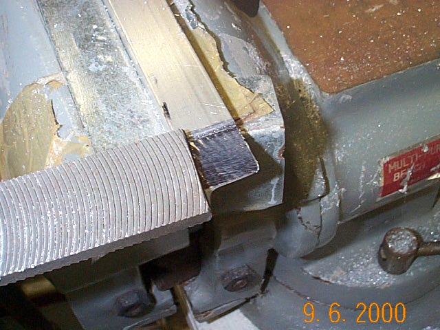
For only the second time since starting the kit, I used the vixen file to file away the ends of the attachment angle so they would fit flush on rib when overlapping the rear angle.
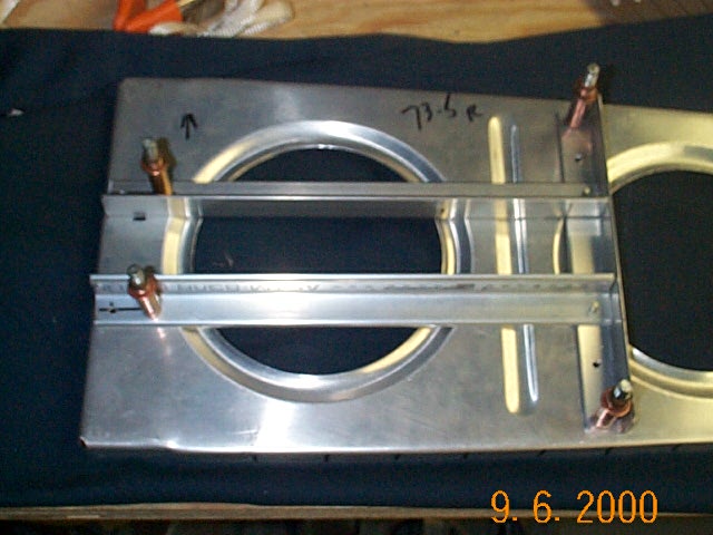
Here is the completed bell crank attachment angles drilled and cleco'd to the rib.
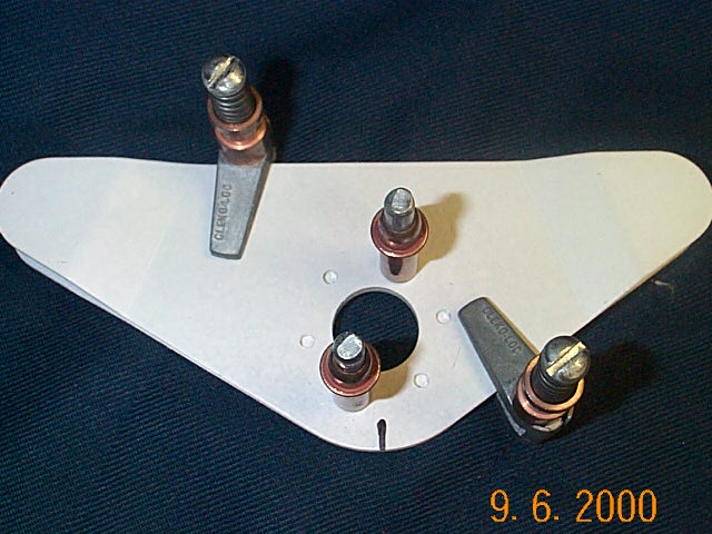
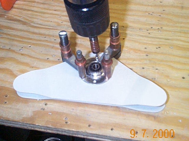

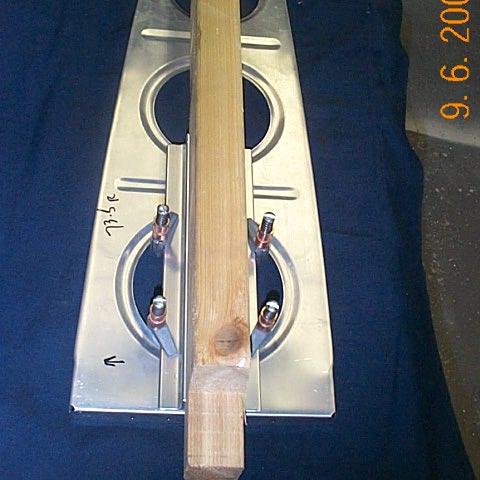
Here, I clamped the pieces together with the bearing and drilled the bearing mounting holes. Don't forget to mark the bearing and the bell crank so you can line the holes up after disassembly.
Initially I couldn't figure out how do drill a perpendicular hole for the heim ends. I stuck a 1/2" piece of plywood in between the metal pieces and drilled them all as one assembly. This ensured that both holes were the same because the metal didn't flex when drilling. It's little victories like this that make the project fun.
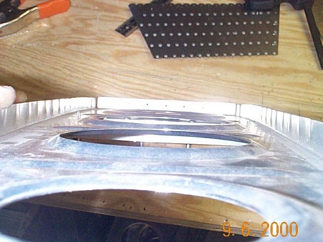
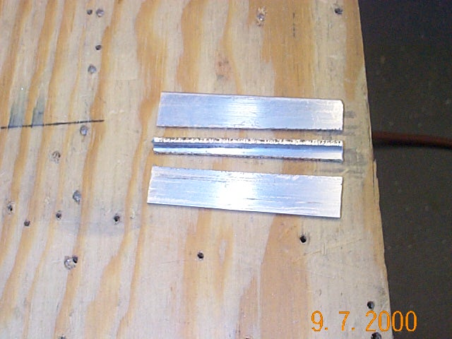
The bearing leaves a gap in the metal brackets so the plans call for a .063 x 1/2 x 1.5 piece of aluminum to be riveted in place. Actually, the plans are rather vague here. They didn't supply the pieces in the parts bag so I cut up a .063x3/4x3/4 piece of angle to make the pieces
The finished aluminum strips drilled and cleco'd in place.