|
|
|
|
|
|
||
|
I was very unhappy with how the left elevator turned out, especially in the area of the trim tab. I compared the appearance of my work to that of many other RV's that I came across. It seems like everyone in the world can bend those little tabs over 'cept me. After obsessing about it for a while, I decided to rebuild the elevator since there were a couple of other imperfections that irritated me also. Additionally, I had a chance to see Chuck Brietigams (Louisville, KY) RV-3 and the modifications he made to his elevator, aileron and rudder trim systems. Very impressive as was the whole airplane. This page is devoted to the rebuild, and plans modifications, that I made on the left elevator and trim tab. |
||
|
|
I built the first elevators and rudder but didn't like how the leading edge roll turned out. It didn't lay as flat as I would have like so I decided to double the number of blind rivets that were used on this one. I cleco'd a rivet spacing tool to the leading edge and this allowed me to accurately mark the location of the new rivet holes. Worked great! |
|
|
|
I didn't get a picture of the ugly looking end tabs on the elevator and trim tab but this is what it looks like after cutting them off in preparation for the hand made ribs. The Orendorff videos make reference to this as does the construction manual, but neither source tell you how difficult (for me anyway) these are to make. You really need some sort of metal brake to do it properly. |
|
|
|
This is the rib I made for the elevator side of trim area. I got hold of some bulk alodining mix call Darado Kote 1 so I will be doing a more consistent job of alodining the parts as seen here. I've got enough mix to make about 60 gallons at less than $2.00/gal. I haven't decided how to install the ribs yet. The end ribs shown in other parts of the plans show it one way but I wonder if there is some drag benefit to installing it the other way. One way will require blind rivets and the other way allows me to use regular rivets. I dislike using blind rivets because it will force me to do more prep work before priming to fill in the holes. |
|
|
|
The is the rib I made for the trim tab itself. The other side of the trim tab will be folded over. Hopefully I won't screw it up this time. I've got the use of a metal brake this time so it should turn out better. |
|
|
|
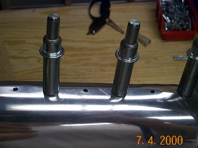
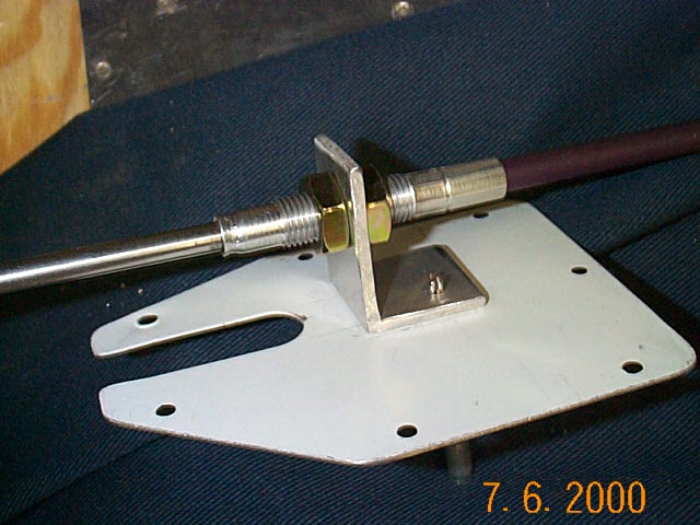
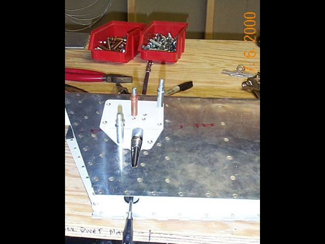
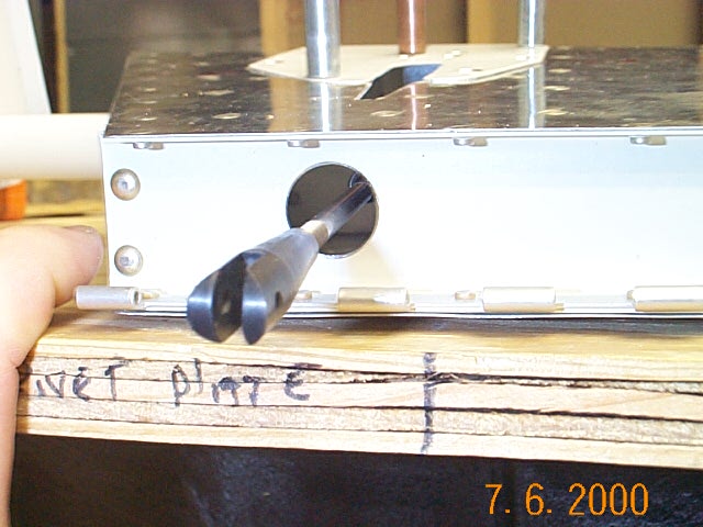
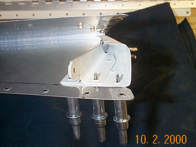
I've decided to make a modification to my trim tab that will hide the trim horn and decrease drag a little (yea, right). Mainly, I think it just looks "cleaner". I saw this successfully done on Chuck Brietigams RV3. I didn't see how he accomplished his modification, but this is my version. After some trial and error, I built a bracket that will mount the trim cable in the correct position. I used some 1/8" angle aluminum that I got from Aircraft spruce. You can see where I used a UNIBIT and drilled a 7/16" hole in rear elevator spar for the trim cable to pass through. |
|
|
|
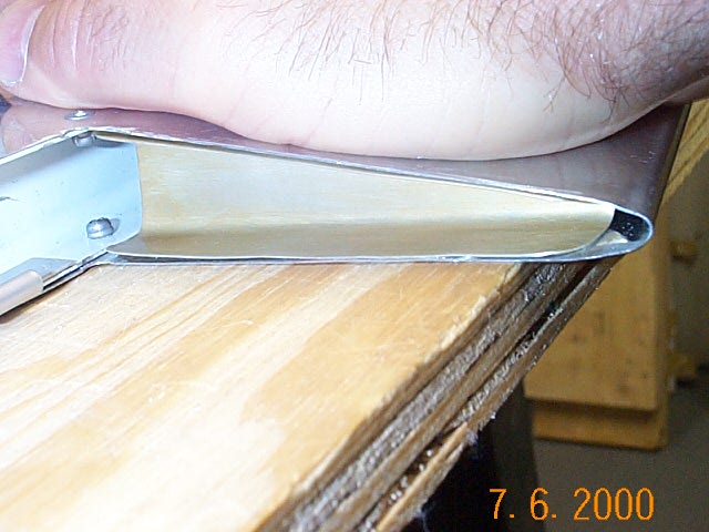
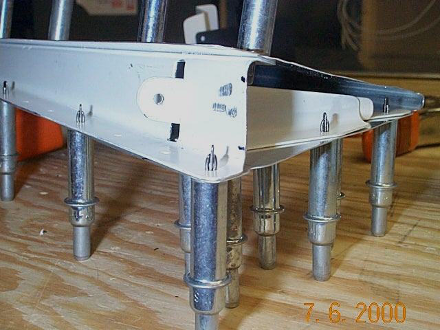
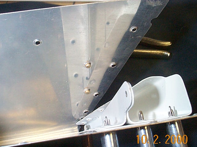
This is an old trim tab with the end cut off. The new one will have the flanges bent over to cover the opening as in the plans. You can see that I have moved the elevator horn from it's location on the bottom of the trim tab to the interior of the trim tab. I first cut a slot in the trim tab spar so the horn can pass through. The trim hinge is not installed yet, but this shows how the trim tab will connect. The potential problem with this modification and electric trim is one of safety. The MAC 8A servo will certainly handle the additional torque necessary due to the decreased leverage. However, the MAC 8A servo has a travel of about 1.2 inches and might cause a problem that elevator travel can't handle in the event of trim servo runaway. I will install the MAC 4A servo that has .7 inches of travel instead. |
|
|
|
Here is the end rib that I had to make. I made it large enough so that the rudder horn would sit on it. If I hadn't done that, and made the rib with regular flanges, I would have had problems with part of the horn hitting the flanges. I laid out the shape of the rib with thin poster board then transferred the shape to the aluminum sheet. |
|
|
|
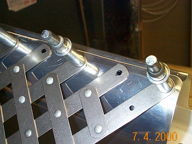
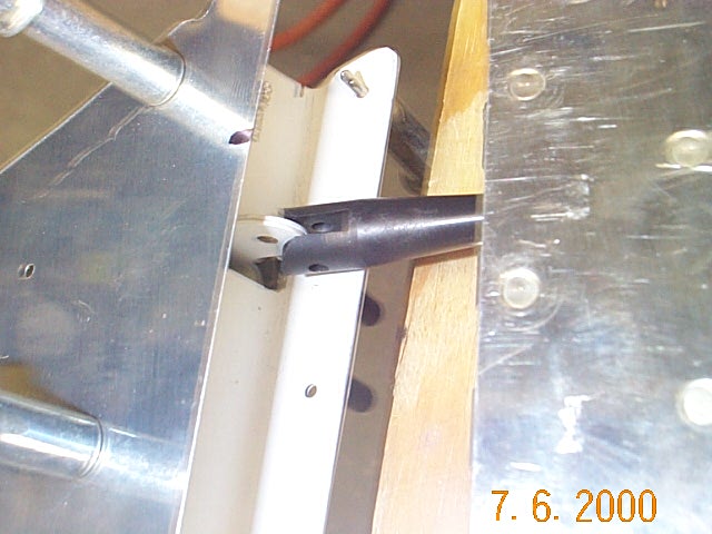
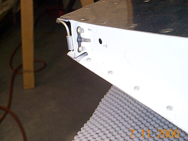
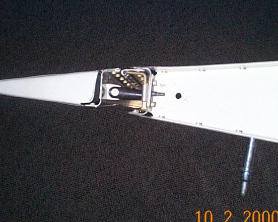
Here is a method that I used to secure the hinge pin. The trim is removed for clarity. I cut off one eyelet of some extra trim hinge that I had and secured the eyelet and hinge rod to the rear elevator spar with a #6 screw. I secured the nut plate with the same rivets that hold the end rib in place, It's an unbelievable coincidence that the hole happen to line up perfectly with the nut plates. I had to drill the nut plates to accept the AN470 rivets. I'll cut the screw to length at a later date. As you can tell, the hinge pin is my second try. The first one worked but looked.......well, you know what I mean. |
|
|
|
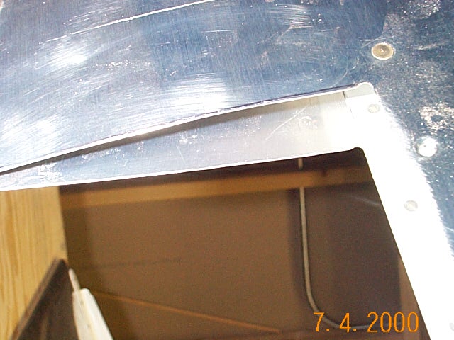
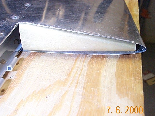
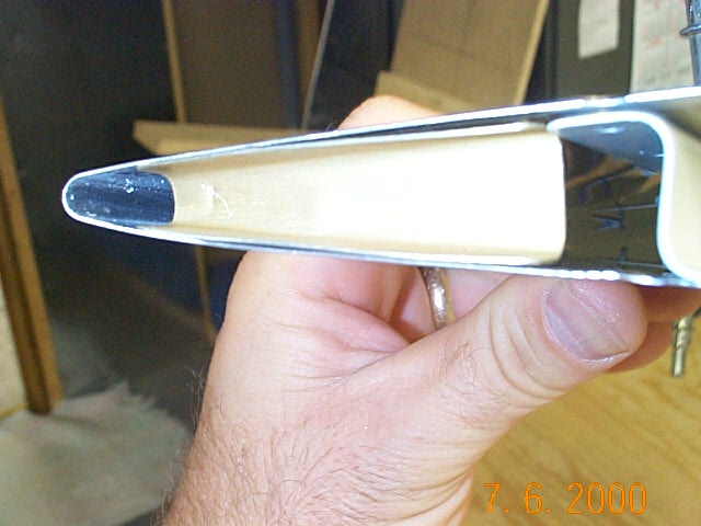
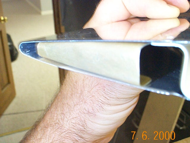
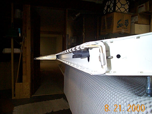
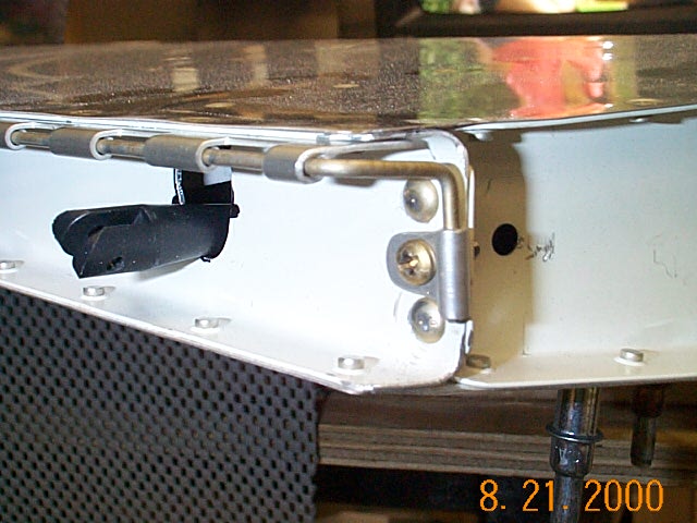
Here is a side view of the finished elevator trim. The elevator horn is well hidden and the air doesn't see it. There was probably an easier way to do it and I'll try to figure that out when I do the aileron trim. |
|