DCP01579.JPG (69433 bytes) DCP01580.JPG (64965 bytes) Installing the Proprietary Software System AOA differential pressure ports is an important part of ensuring the instrument works correctly.  There are  upper and lower pressure ports that are drilled .040 in size. I don't have a drill bit that small, so I called PSS up and  Jim was very helpful.  He said the reason for the very small bit was to keep bugs and other critters out of the ports and that the 1/64" bit that I had on hand would be fine as far as instrument operation is concerned.  He restated that the actual location of these ports in relation to each other  is critical.  For this installation, a location 12" back from the leading edge has been determined to work best.  In order to locate this position.  I clamped my Smartlevel in a level position on the leading edge tip and measured down (back) 12" from the leading edge on the top and the bottom main skins.  
DCP01572.JPG (66377 bytes)

  DCP01573.JPG (62438 bytes)

  DCP01574.JPG (57684 bytes)

After the port position was located, I drilled the holes and fit the port hardware

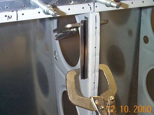
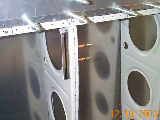
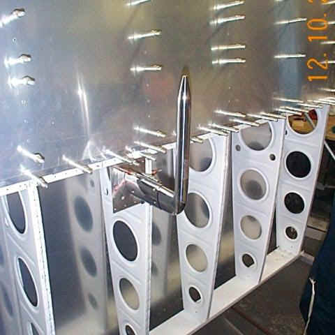
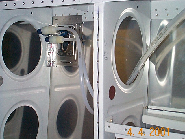
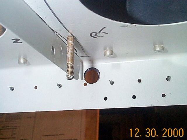
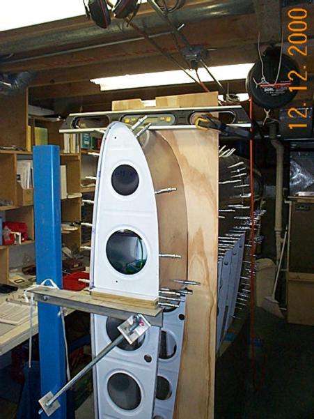
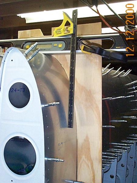
There is a drain for the top port that exits on the bottom of the wing skin. Because of this,  the bottom port is not directly under the top port.  In this installation, it is mounted approximately 2" to the inboard side of the top port so the drain hole does not interfere with the bottom port.  The tubing shown will be connected to the AOA computer in the cockpit along with two other tubes that are "T'd" into the pitot/static lines.

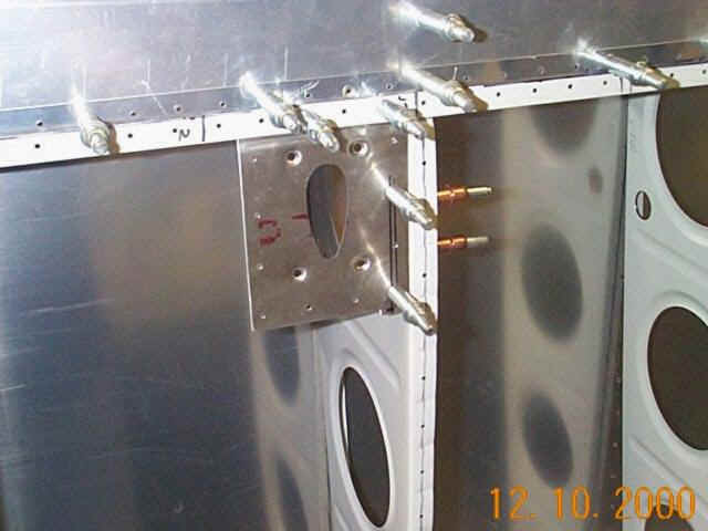
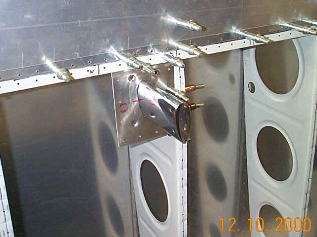
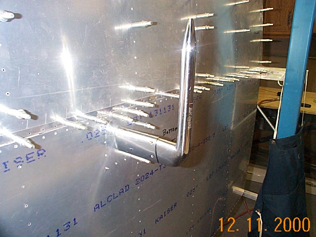
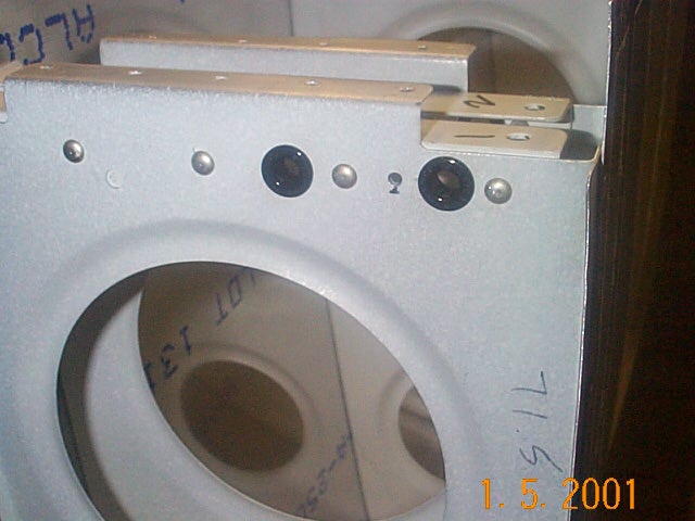
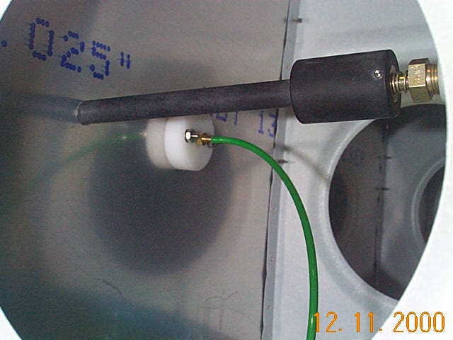
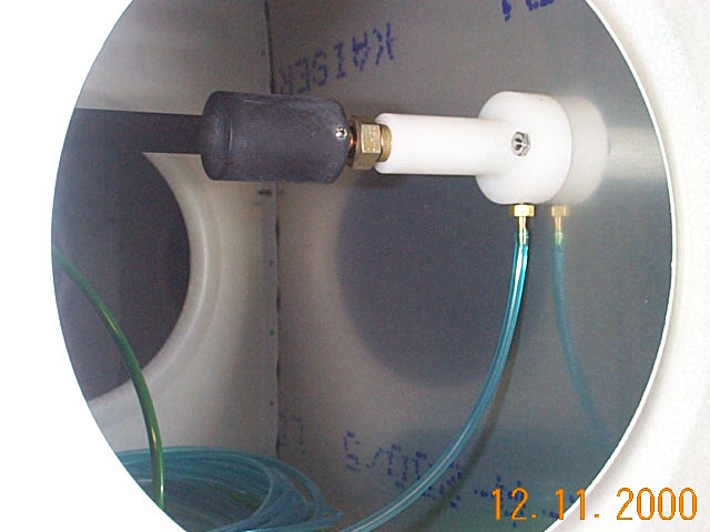
The drain port is used like a fuel drain (in fact it's the same as the one Vans ships) and needs to be checked before each flight.  Here you can see the bottom pressure port and the drain.  I will trim the drain (black) so that it is flush to the skin and the screws that hold the pressure ports in place will be dimpled  and sealed with Proseal or Permetex Gasket Sealer.


Pitot Tube Installation
DCP01564.JPG (72497 bytes) wpeE.jpg (26995 bytes) wpe10.jpg (24902 bytes) wpe14.jpg (29037 bytes) wpe16.jpg (24708 bytes) To avoid interference with the tie-down rope, I decided to install the pitot tube as far outboard as I could.  With the bottom skin in place, I reached through the inspection hole to ensure my arm could reach far enough to remove the pitot connections if service was necessary.  

The Gretz installation kit is very complete and includes everything you need except one small piece of .032 angle.  This piece was quickly made out of scrap stiffener angle and will be held in place to the rib with 4 AN470 rivets

The next step is to locate the mounting plate to the spar flange and, using the pre-drilled skin holes, drill the mounting bracket.  I then removed the bracket and used the template provided to lay out the remainder of the holes that will rivet the bracket to the angle and the bottom main skin.

Next I installed the corner plate nuts (provided) to the pitot mounting mast and ensured that the double plate (not shown behind the mounting plate) and mounting mast fit correctly.  A small amount of filing on the doubler plate was necessary to clear the angle.

The pitot tube is then slipped on for a trial fit and will eventually be held to the mounting mast by 4 #8 screws.

DCP01575.JPG (81035 bytes) The final step was to install the bottom main skin and back drill the remaining mounting holes and cut the opening in the skin for the pitot tube.  I've still got to drill and dimple the 4 holes that will hold the pitot tube in place.  I need to order and/or scrounge up a #6 dimple die.
DCP01628.JPG (64208 bytes) DCP01629.JPG (72903 bytes) DCP01778.JPG (80094 bytes)

DCP01627.JPG (65712 bytes)

I've decided to use Poly Flow for the complete Pitot/Static system.  By doing it this way, I save myself the trouble of mixing and matching between aluminum tubing and poly tubing later on.  These pictures show what hardware I used to connect the AN fittings on the AN5814 pitot tube and the nylon tubing.  Lest you think I have any brains at all, be advised that I got this idea from the RV-List archives circa 1997 from Dave Barnhart.  As Dave said in his message, "It's kind of a kludgy transition, but it works".  I've tried to show all the part numbers so, #1,  I don't forget and, #2 maybe someone can benefit from this.  The pictures show straight AN816 Nipple fittings but I have ordered a couple of elbow fittings to replace them.  There will be a service loop of tubing in this area for future maintenance.


Here is a picture of the 1/4" snap bushings that the Poly-Flow tubing will run through.  I love these little bushing, you drill a 7/16" hole with the unibit and they "snap" right in.  You can also see the "oopps" hole.  It's not the first one and I'm sure it won't be the last.

Additionally,  I will be installing a fuselage static port with a selector valve as a backup.  I've heard that the 5814 pitot/static tubes have an error because of the built-in static port.  This setup will allow me to verify that theory.

DCP01782.JPG (67065 bytes) DCP01783.JPG (66726 bytes)

Here are the Pitot/Static lines being run on the forward side of the main spar.  I'm using polyflow tubing instead of aluminum because it easier to run and work with.


Here is a close up of the clamps I made to secure the poly tubing to the spar. I just used some scrap laying around hence the different sizes.


Leading Edge Skinning
DCP01590.JPG (99301 bytes)

To start the leading edge skinning I removed all the cleco's holding the ribs to the main spar and placed the leading edge assembly in this cradle  I made from some 1/4" plywood.  I held one of the 10" wide pieces up to the end of the leading edge and traced the shape of the airfoil onto the wood.  I then clamped the two pieces together and used the band saw to cut the shape.  I used drywall screws and attached them to the fixtures I used for the vertical stabilizer.

I de-burred all the holes in the skin and the ribs.  I also dimpled all the ribs and skins and riveted the assembly in about 4 hours.   That seems like a long time to me but then I had to make the cradle also.

DCP01616.JPG (55501 bytes)

This little hole proved to be a bigger hassle than you would think.  I had clecoed the leading skin on when I realized that I hadn't drilled the tie down hole.  I then had to remove all the leading edge clecos and take off the tie down bracket (not shown).  I used the existing hole I had drilled in the main spar flange and marked the leading edge skin.  I then drilled a pilot hole and opened it up with a unibit.  While I had the tie down bracket removed, I riveted the holes I wouldn't be able to get to when it was installed.  I realized I have an edge distance problem with the one rivet, but there's not much I can do about it at this point and I'll have to live with it.  If you follow the plans (like I didn't) you won't have a problem.

DCP01594.JPG (66896 bytes) DCP01595.JPG (98853 bytes) I heard that riveting the skins without help would be tough but it wasn't too bad.  The last 2 or 3 rivets at the leading edge are a little touch to get at but other than that all the rivets look good and I didn't have to drill any out.

The extra holes you see in the top and bottom skins are for the AOA ports.  I'll be sealing them with pro seal when I do the tanks

Now on to the second leading edge.  I won't document it's construction since it's no different than the first except there is no AOA port.

DCP01668.JPG (92445 bytes)

Here are the wings in place with the tanks attached.  The main wing skins still need to be riveted and the attachment screws still need to be drilled and the nut plates attached for the tanks.