|
Capacitive Fuel Senders |
||
| |
||
The construction manual does not cover the installation of the optional capacitive sends. Vans sends you a drawing of the installation and that is enough to get the job done. Basically, the senders use two plates mounted to tank ribs (2nd rib outboard and 2nd rib inboard) and connected together with a wire. The wire goes to a BNC connector mounted to the inboard rib near the vent tube fitting. There are no moving parts in this setup but it has to be installed when you build the tanks and cannot be retrofitted to an existing tank (at least not this design). By the same token, if a wire breaks or comes loose on the plates, it can not be repaired either. If that ever happens ( I doubt it will), I'll have to either rebuild the tank (not) or install a float sender. These type of senders also require you to use the Electronics International fuel gauges (at least these are the only ones I'm aware of). |
||
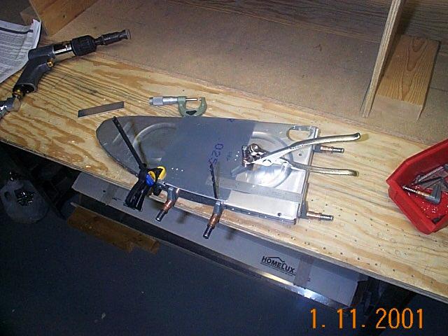 |
The sender plates needs to be positioned accurately on the ribs. Here you can see that I'm using a ruler to measure from the rear rib flange and the top rib flange. I'm using a drill bit to accurately locate the plate along the whole edge of the rib. I then held the plate firmly in place with my hand while I drilled the three mounting holes. |
|
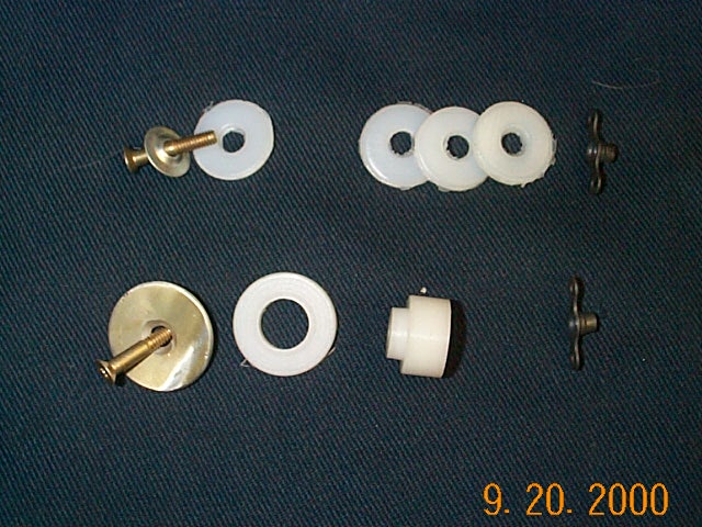 |
It's important that the aluminum sender plates remain isolated from the rest of the tank. The kit that Vans sends consists of about 8 individual pieces as shown in the top of this picture (poly tubing not shown) RV builder, Peter Laurence in S. Florida, sent me the plans and a sample piece that he made to eliminate several of the pieces. I used the lathe and a 3/4" piece of Delerin rod to make my own isolator bushings. |
|
 |
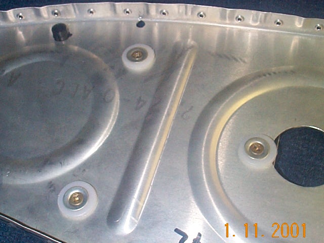
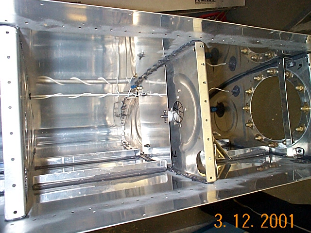
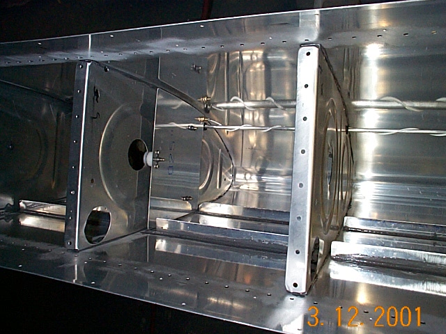
These pictures show both sides of the rib and how
the plates attach to the rib.
Warning!! At this point, hopefully you haven't already Proseal'd and riveted the stiffeners to the tank skin. The ribs with the sender plates will not fit into position unless the stiffeners are cut for clearance. The plans do not show this. |
|
 |
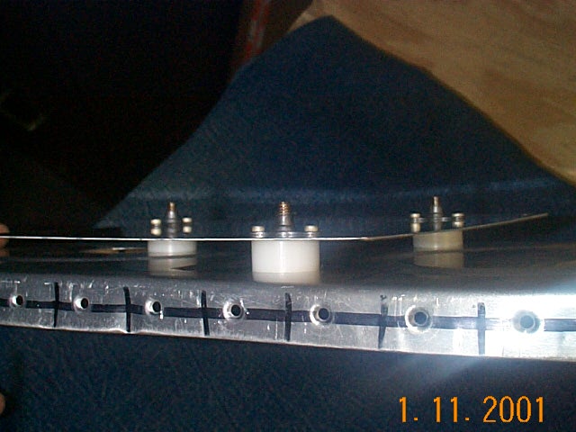
In this photo, you can see how the stiffeners need to be trimmed in order for the sender plates to fit. This is a lot easier if you do it prior to prosealing the ribs in place. You'd think I'd learn after the first one. I didn't and had to trim the stiffeners in place. The chips and aluminum dust created then sticks to the Proseal. I will coat the chips that are stuck in the Proseal with more Proseal so it doesn't come loose. | |
 |
Here is the second fuel send plate. The wire from the first plate attaches here then goes to the BNC connector mounted on the first inboard rib. | |