|
|
|
|
|
|
|
|
|
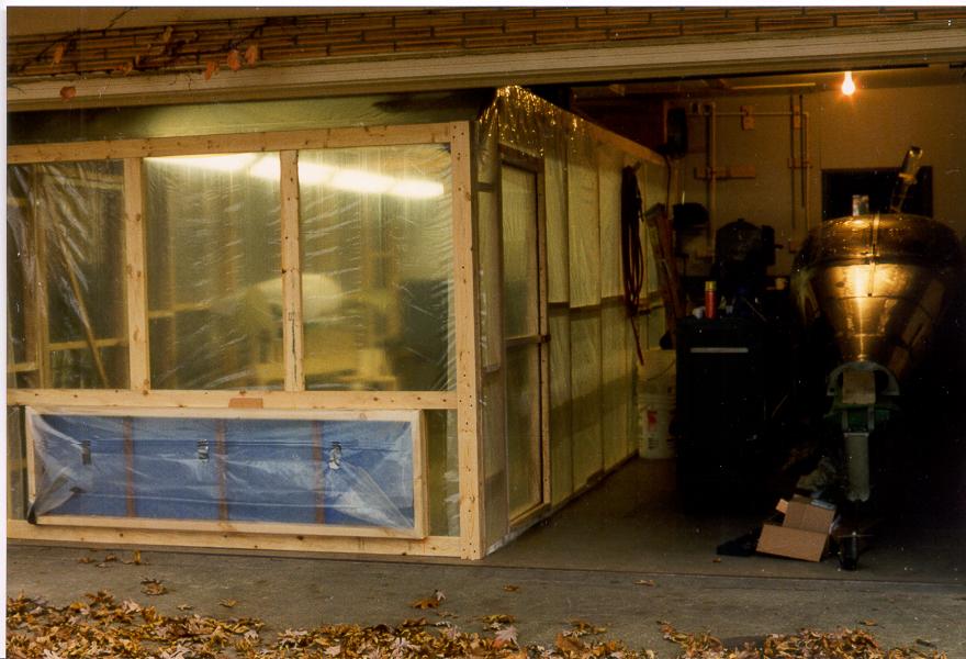
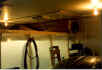
Paul built this very nice paint booth in his
garage. He uses two attic fans from Home Depot so suck warm garage air and
push it through filters on top of the booth. Additional filters
(shown) are used on the exit air side. The garage door is closed low
enough so that only the filters are exposed. |
|
|
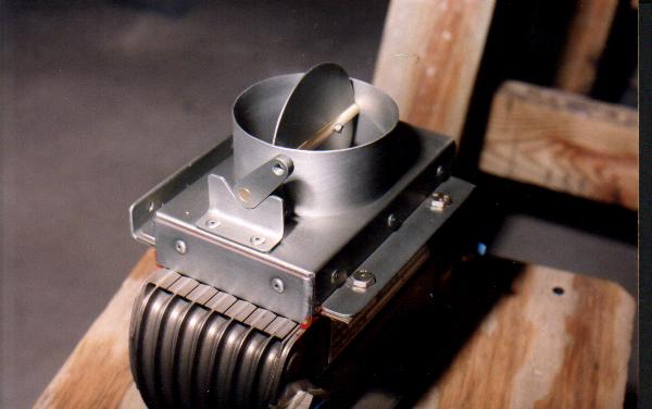
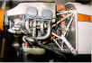
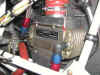
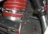
Take a close look at the scat tubing that
runs to the oil cooler. Paul installed a control device that
regulates air through the cooler to control oil temps. As you can
see, the rest of the engine compartment is just as sanitary!
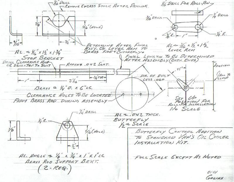
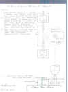
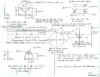
Paul recently drew up plans for his heater control
door. While Paul hasn't had any oil temp problems this winter he's
holding off judgment until the hotter weather arrives. Click the picture
at left to see the drawings.
UPDATE
07/ 2001 Paul reports that even
on 90+ degree days oil temps are staying well under 210
degrees. It would appear that the remote mounted oil
cooler, oil cooler door and scat tubing are working great.
The second drawing shows how to make the shaft the
butterfly attaches to.
Look at these drawings would you? CAD stuff is
nice but there is nothing like a professional blueprints done by
hand. Each one has it's own personality.
|

 |
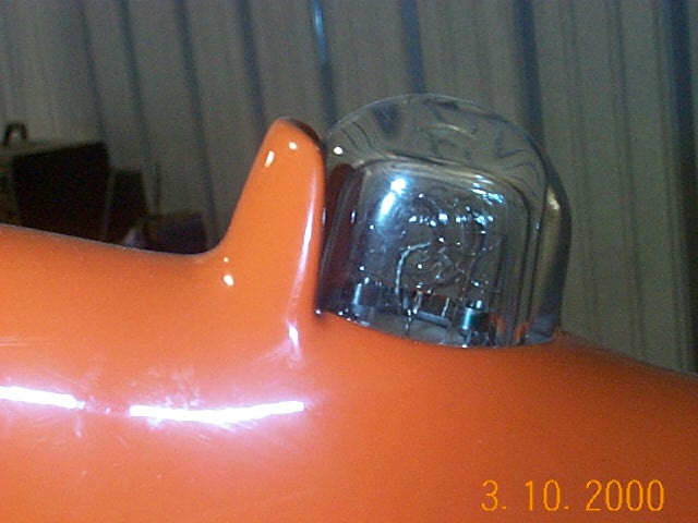
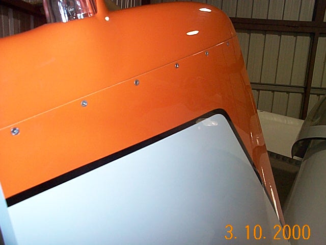
In addition to wingtip strobes, Paul likes
the look and safety of a Vertical Stabilizer strobe. He dealt with
the issue of excessive flash in the cockpit by building this really cool
fairing into the VS. Paul used #4 screws to attach the VS tip for
future access. My initial plans will be to use the same technique for attaching my
VS tip since I will be mounting my VOR antenna in on the VS
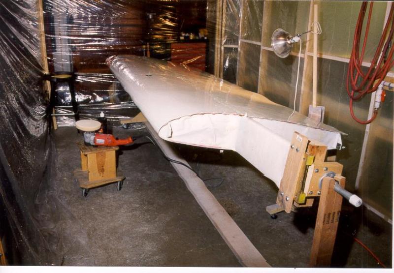
Notice the clear coat paint job. The pictures do
not do it justice, but this is one immaculate paint job. It is glass
smooth and deep looking. |

 |
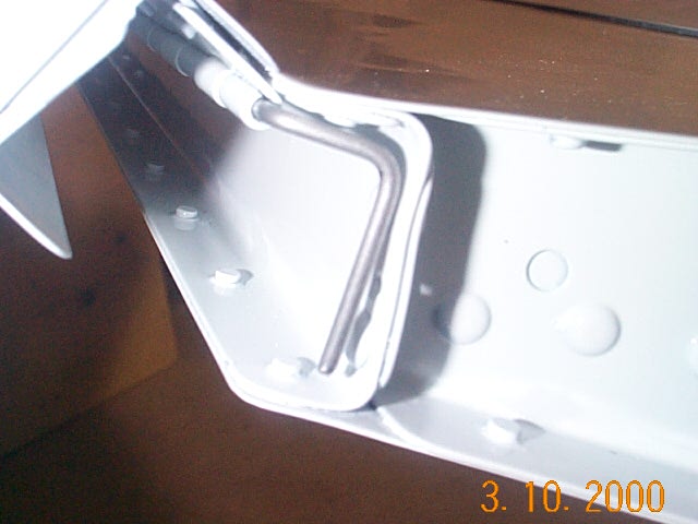
Paul's workmanship is first rate everywhere!
A couple of techniques he used for securing hinge pins on the cowl and
trim tab. Note the inner seam where the cowls come together.
Beautiful! |
 |
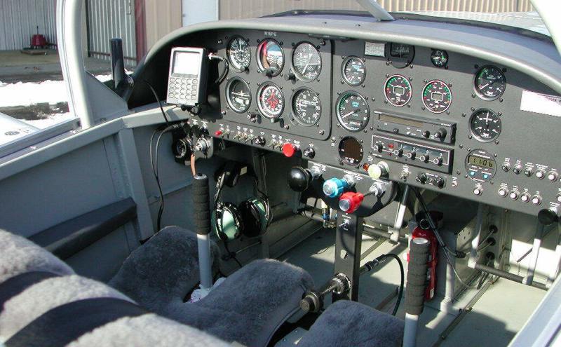
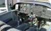
I really like the look of the paint on Paul's
panel. So much so that I would like to duplicate it on my
plane. It's not black but more like a dark pewter or gunmetal
color. Paul said he used a can of can of Rustoleum spray paint
designed for lamp posts but used light coats. Nice overall VFR
panel.
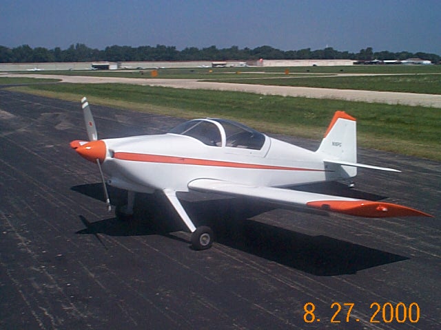
Paul's -6 uses an O-320 and C/S prop. Not seen in
this picture is a unique defrost system. At the bottom of the
inside windshield, Paul built a fiberglass lip and cut slots every few
inches. If necessary, Paul can route the cabin heat to this area to
defrost the windshield. |
 |
Paul recently got his FAA signoff with only
two minor squawks. I missing screw and one safety wire on
wrong. Paul will be building his tail wheel time in a Citabria then
scheduling some more time with Mike Seager in Portland. After that
he'll take to the skies. It must be tough looking at that beautiful
plane in the hanger but having to wait to fly it even though it's ready to
go.
Paul has matching wheel pants ready but will leave them
off for the first flights. |
 |
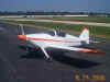
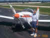
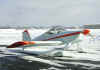
Here are some updated pictures of
N16PG. At this point I think the plane has about 7 or 8 hours on
it. As you can see, the weather has not been cooperating very well
here in the Chicago area. The wheel pants are on and looking very
good. Paul also bought a new Nikon Digital Camera, so these pictures
are better than I could have taken with my old Kodak digital.
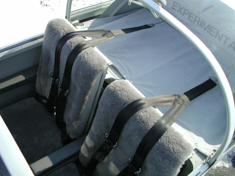
Paul has also installed some sheepskin seat covers and
they look great. As soon as he gets his hours flown off I'll get a
chance to sit in those things and check them out. The baggage
compartment cover is also a nice touch to help give the plane an overall
professional appearance. |
 |
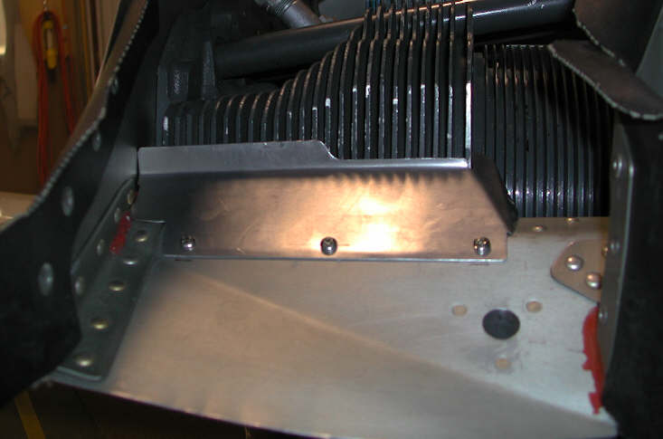
The top picture is the original baffle for
the right cylinders. The rear cylinder was running hot so Paul
modified the baffle to deflect air over the front in an attempt to cool
the rear cylinder more. It helped quite a bit, but again,
warmer weather will be the true test. |
|
|
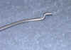 |
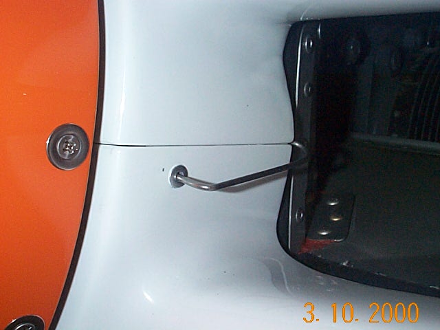
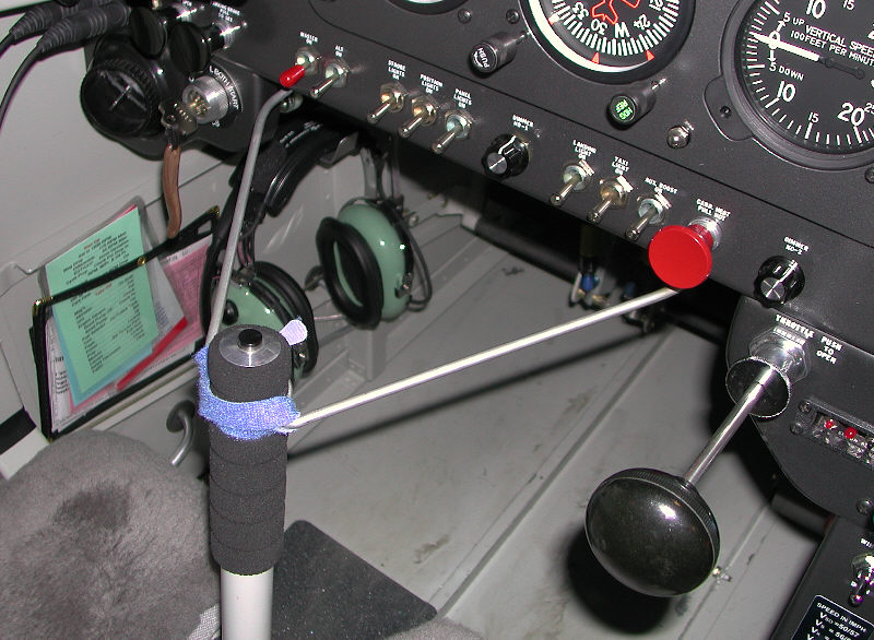
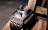
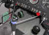
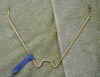
You have to love some
peoples ingenuity!!
Paul had a need for a gust lock and
didn't find anything he liked that was simple and easy
to use......so he designed his own. They don't
get much simpler or easier to use. It stores in
his map pocket and I can attest, the control surfaces
WILL NOT MOVE when this simple device is in place.
The pictures pretty much tell the
story. There are two holes drill in the flange
at the bottom of the instrument panel and that's where
the end of the control lock slides in. In
effect, the instrument panel is keeping the stick from
moving.
The control lock is made from an old
fashioned coat hanger. |
|
|
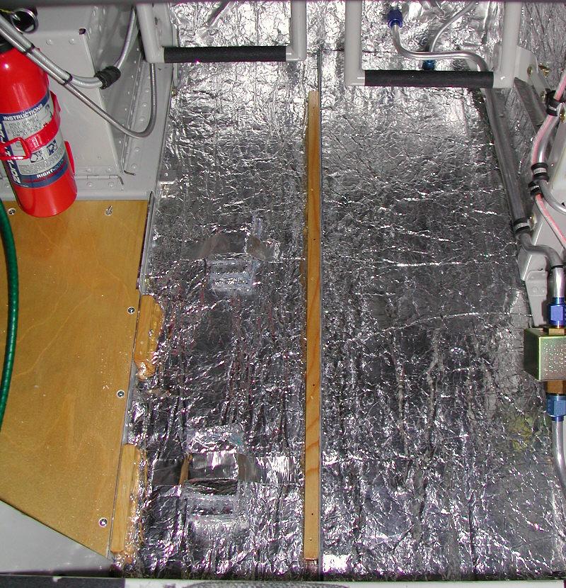
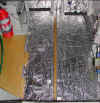
Sub Floor and
Insulation |
|
|
|
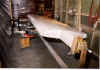
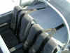
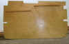
This is the method Paul
chose to provide an insulated, level floor
that will also attach carpeting. Paul like the
natural resonance absorbing qualities of wood, hence
it's use instead of aluminum. The penalty
is 2.5lbs. per side and 8lbs. for the center
section. This includes the plywood, insulation and
mounting strips.
|
|
|
|
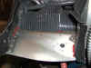
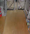
The insulation layer is
in place and the spruce strips for attaching the
plywood are screwed to the side of the Al. angle
supporting the floor. There is also one Al.
angle clip with a tapped hole located at the mid
point of the battery.
|
|
|
|
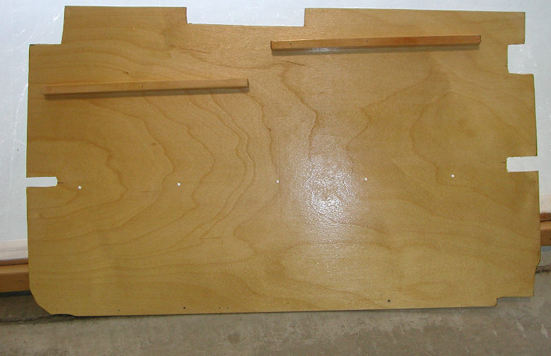
The mounting strips are
spruce 1/2 X 5/8 X length to suit. The plywood
is aircraft grade finished Birch 3MM thick.
The insulating product is called The Insulator
manufactured by Unlimited Quality Products
double foil side single layer. All above
purchased through ACS.
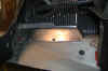
This shot shows the
support strips mounted to the bottom of the plywood
at the outboard side. The plywood is held down
because it fits both under and over the corner Al.
angle.
|
|
|
|
The
plywood fits under the corner angle at the front R/H
side and on top the angle from the fuel pump
rearward.
|