|
|
|
|
|
Mark Phillips Builder Ideas |
|
Here's a few things I
dug up after rummaging around in my "wing" period- use at your own
risk!- some of the stuff I come up with strikes me as silly at
times, but every now and then something that "might" be useful
escapes the dark, twisted abyss of my remaining brain cell!
|
 |
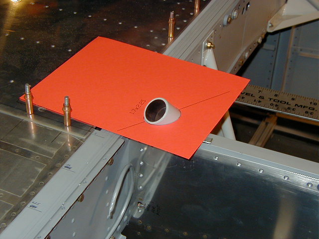
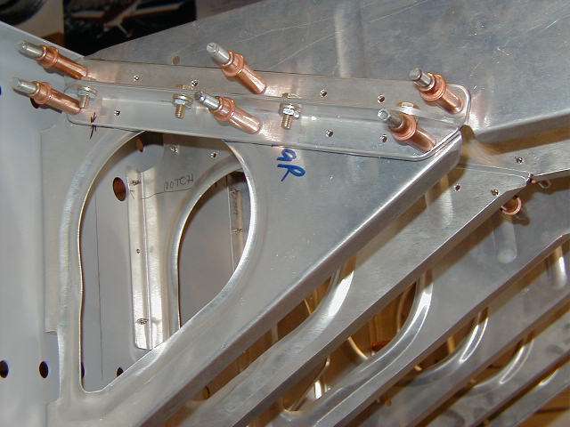
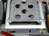
Photo labeled Fuse 129-(not so useful for y'all
rear-wheelers) is a template for cutting the holes in the front skin
for the gear leg mounts. With the mount in place, I took some rough
dimensions for the width and length of the ellipse resulting from
the tube passing through the skin, and drew one up in AutoCAD,
printed it on heavy paper, cut it out and after a few trial and
error sessions, got it darn close. The resulting dimensions are
printed on the paper next to the hole, and an extended centerline
through the ellipse gives you a fold line to make it easier to cut
out. Once the fit was right, I drew the outline of the sheet on the
skin aft of the spar so I could put it back in the same position
after removing the mount and installing the forward skin. Trace the
ellipse on the skin and chop away... Came out quite nicely, thank
you! And it's recyclable! Flip it over for the other side- tada!
PLUS- you can fold it up, stuff it in an envelope and snail-mail it
to the next "victim"! |
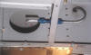 |
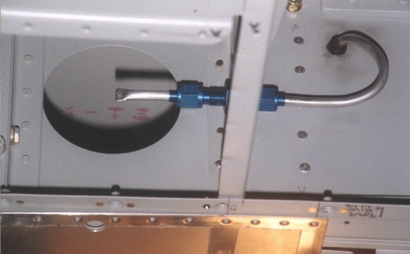
Photo Pitot2: Drag reduction 101- I located the
fitting for the pitot tube in the rib inboard of the access hole.
With the cover off, you can insert the creatively-bent pitot tube
from the inside of the wing (photo shows a short tube with the end
crimped where the pitot tube will attach) and thread it through the
hole shown in the spar flange. I'll use a snap bushing where the
tube goes through the hole. Not sure how this will "fly" in
practice, but my Tech Advisor didn't see any problem with it... |
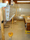 |
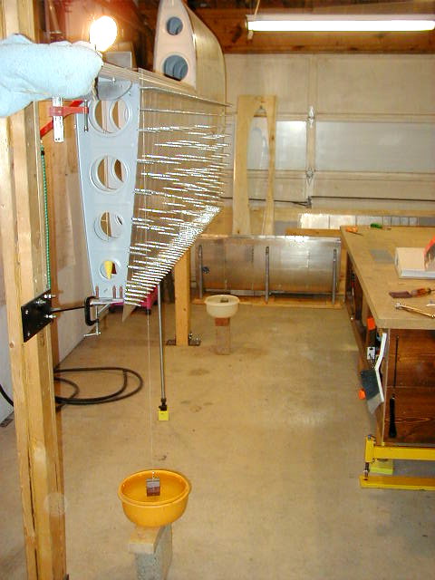
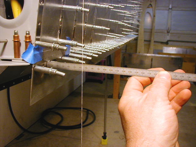
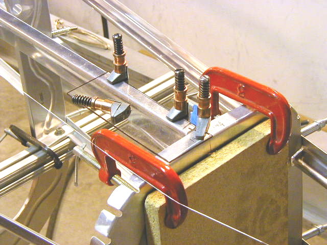
Photo Rwingalign05 & 06: After all the agonizing
folks do over whether their wings aren't twisted (like me!) I think
I figured out a decent way to check before riveting the final skins.
Drop a line of dental floss (this stuff is god-awful strong- hey!
lightweight rudder cables!!) over the top of the spar at each end
with a heavy weight on it. I used my elevator counterweights and
stole the shop dogs' water bowls to stabilize them, (and before you
PETA types start yowlin', yes I washed the bowls out afterwards!!)
then taped a 6" scale on the skin butted up to the rear row of
cleco's to get a common measuring point on each end, then measured
from the skin to the line- holding the scale level helps... |
 |
| |
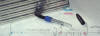 |
Wingribstax2: Who named these photos, anyway?! To
draw centerlines on stuff, take a handy-dandy sharpie, wrap enough
tape around it to set the height of the tip above your work surface
when the pen is laid on it's side, hold the part flat on the table
(wing ribs shown here) and run the pen all the way around the part.
Took maybe 3 minutes do all the ribs, & has been used MANY times
since... |
| |
 |
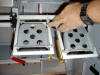
This photo shows a technique were I use a piece of
Lexan instead of aluminum to simulate the skin for positioning the
rib. Using the Lexan allows me ot view the marks that I might
have made to help position the pieces. Works Great!! |
| |
 |
When cutting and making the splice piece for the
center (F-619) seat ribs, I used some angle bolted together and
riveted to the ribs |
| |
 |
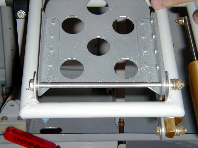
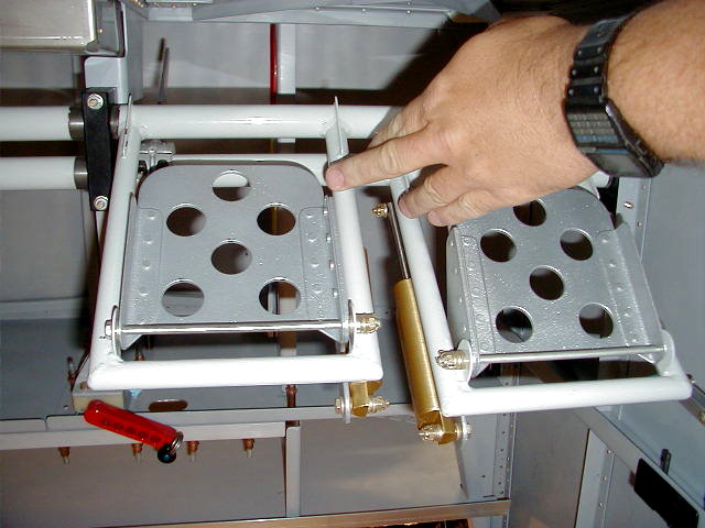
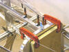
Mark had some concerns about the single bolt on each side of the
rudder pedals. Binding and asymmetrical wear concerned so he
used a long -60 bolt with a castle nut to keep binding to a minimum. |
 |