I'm not sure what Jim Jewel does for a living but it's a sure bet it has something to do with drafting or engineering. Jim sent me some very nicely drawn prints for plans and modifications that he's made or will be making to his RV-6A. I should get some darker drawings in the near future and I'll post them as they become available. In the interim, have a look at these pictures and send Jim an email by clicking on his name above.
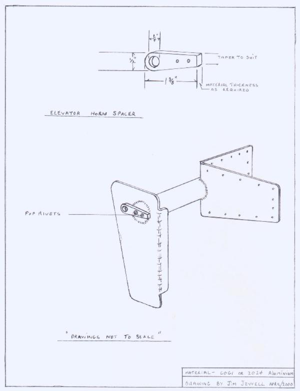
The plans call for using some washers as spacers when attaching the elevator control horns to the HS center bearing. Inserting washers can be frustrating as well as "cheap looking" so Jim came up with this modification to hold the spacer in place and allow for removal and reinstallation of the elevator without all the fuss of messing around with washers.
"The motivation for the elevator horn spacer was simply to make the final assembly and future servicing of the aircraft easier I have not yet looked into weather the design of the control tube Heime(SP.) joint mounting might also require spacers. If needed this concept could possibly be used there also." Jim Jewell
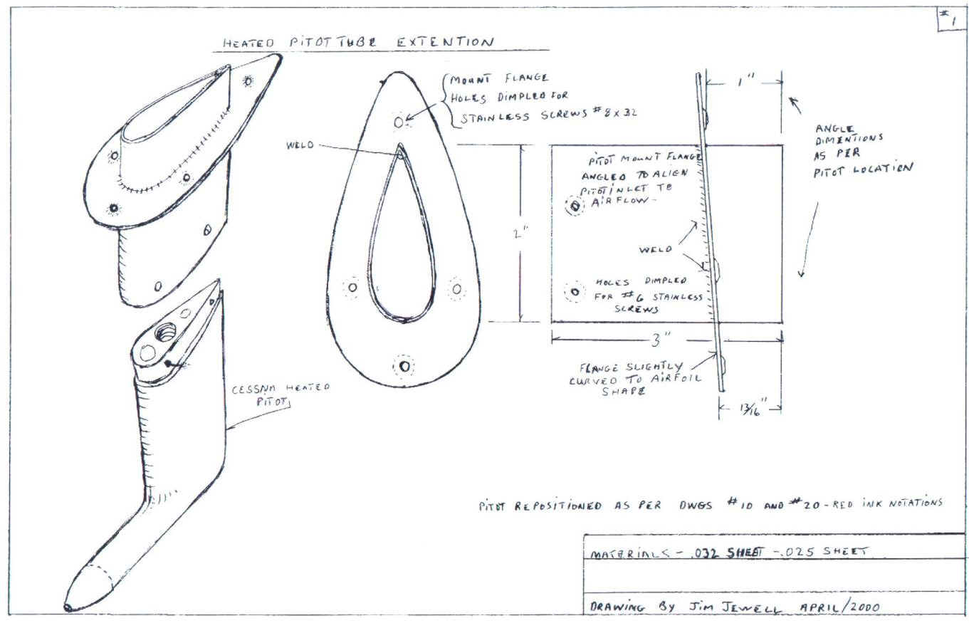

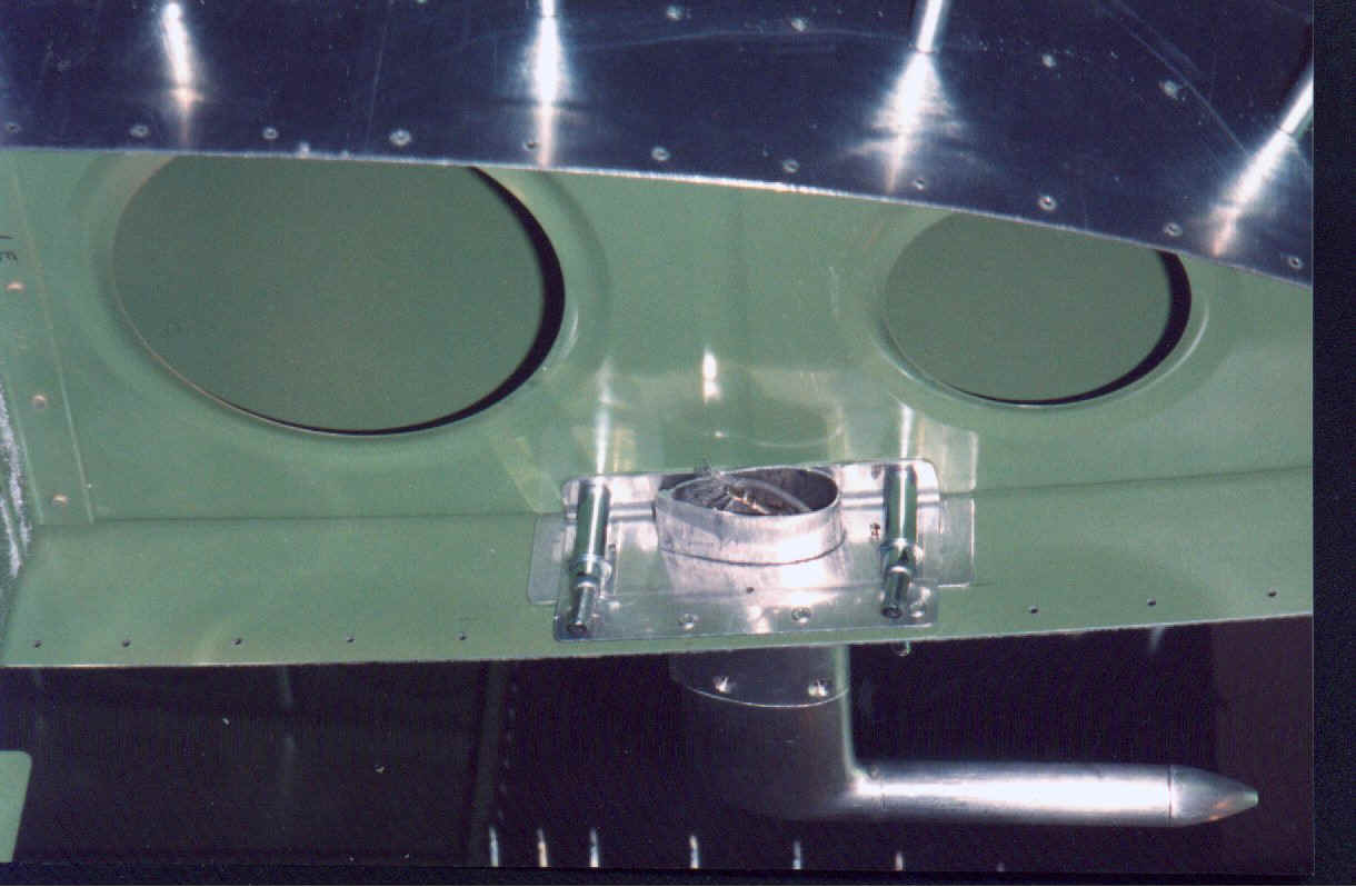
"I chose to move the location of my heated pitot inboard to the area betweenW-4091-L and W-408-1l (the two close ribs outboard of the fuel tank) I also chose to move it forward about 8". The pitot when mounted ended up fitting very firmly in place. Its tip is behind the leading edge by about 6" and clearly out in the un-pressured air. This choice of position may or may not have been wise, time will tell. The strength of the mounted pitot indicates design overkill. The flange up onto the W4091-L could be likely be eliminated. Also, the spacer could be shortened". - Jim Jewell
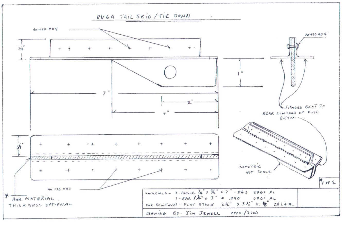
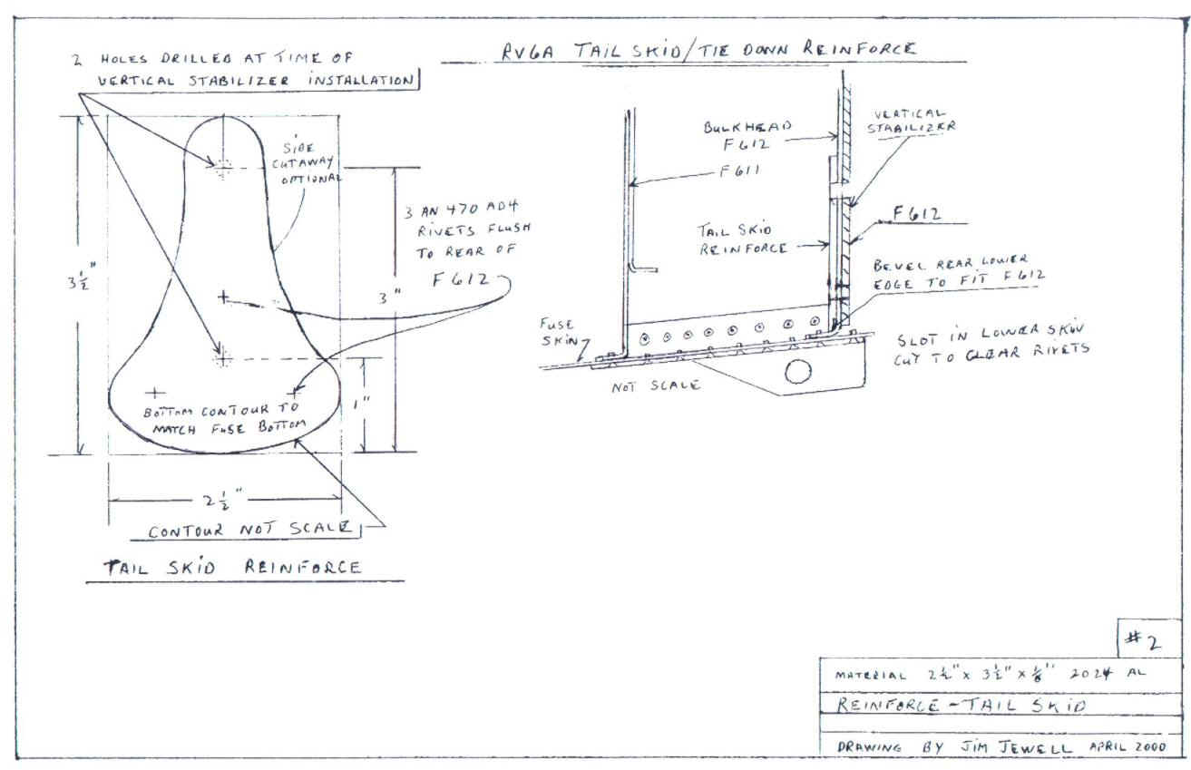
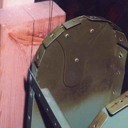
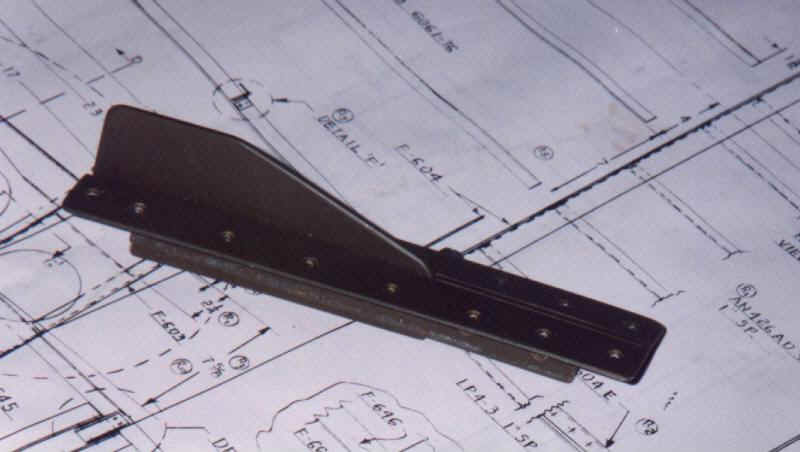
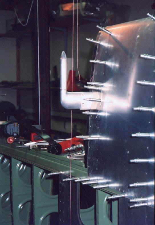
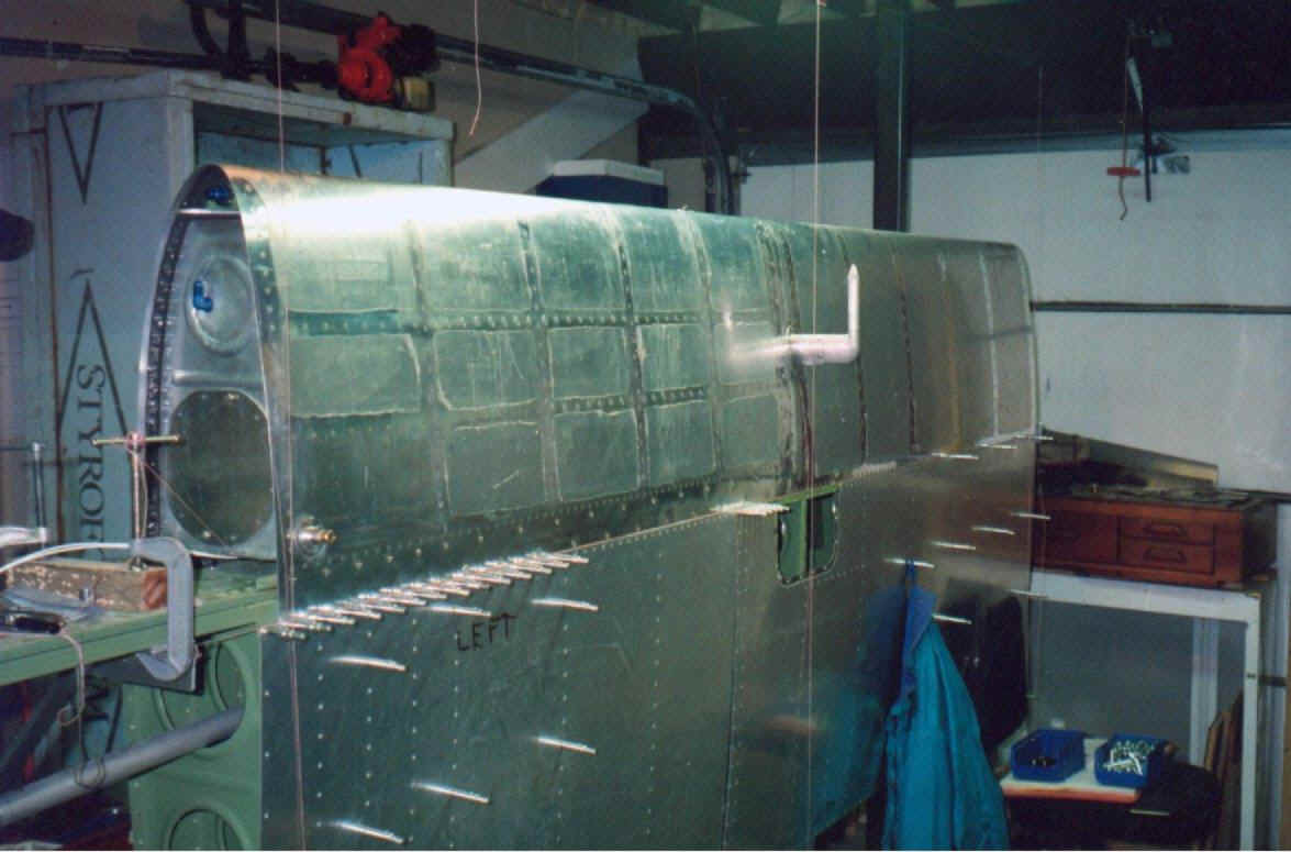
Jim wanted a system, other than a simple tie down ring, that would protect the tail in the even of over-rotation on the RV-6A during takeoff or landing. Jim came up with this bracket that serves duty as both a tie down point and protection for the tail. It seems to me that this concept could be adapted to the -8A and -9 as well.
"The Tail skid / tie down came into being because the SS. unit
supplied by Van's A.C. seemed heavy and looked to me to add to parasitic
drag a bit. It also seemed to present the possibility if dragged on the
ground hard of being bent back and interfering with the rudder. Most
Pilots would never do such a thing I know but if it could happen I might
just be first to do it. I did consider making the tie down flush and
retractable by mounting it on a pivot bolt off center to the rear of
center of it's mounting. after toying with the idea a bit I favored the
K.I.S.S. principal. As designed drag is reduced somewhat and some
protection for contact with the ground is dealt with. For repair the
unit's mounting rivets can be drilled out. The unit depicted in drawing #1
will then drop out with little
effort. After service the mounting holes can be drilled to #30 size,
machine countersunk and flush pop rivets used for re-installation."
- Jim Jewell
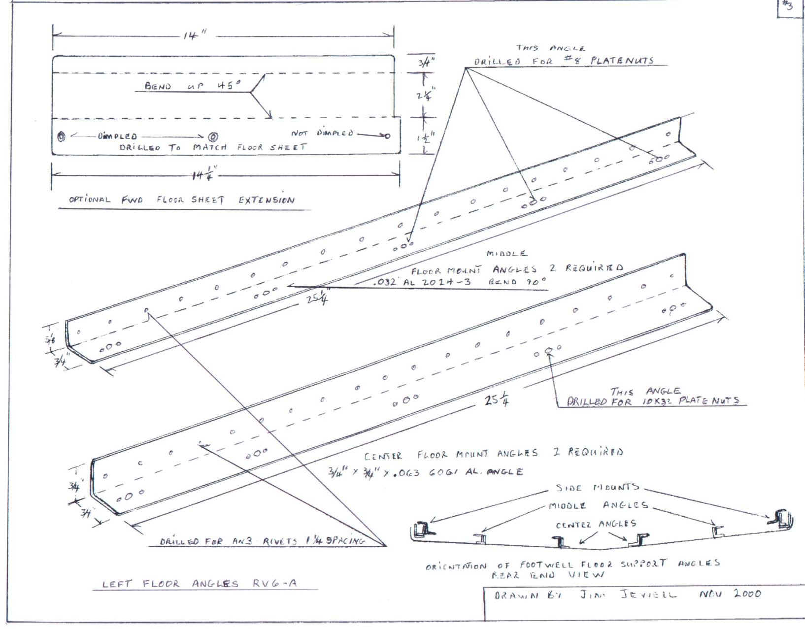
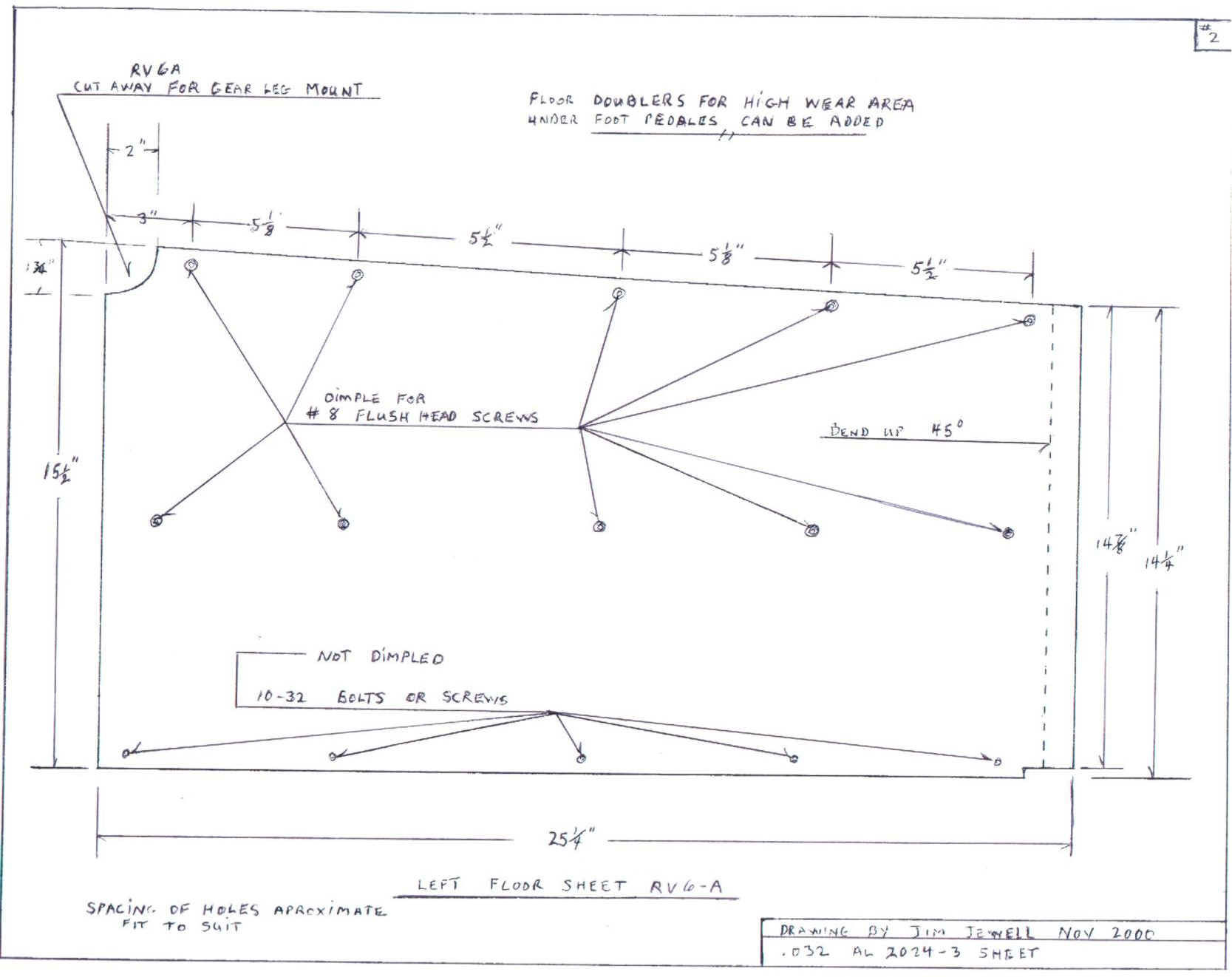
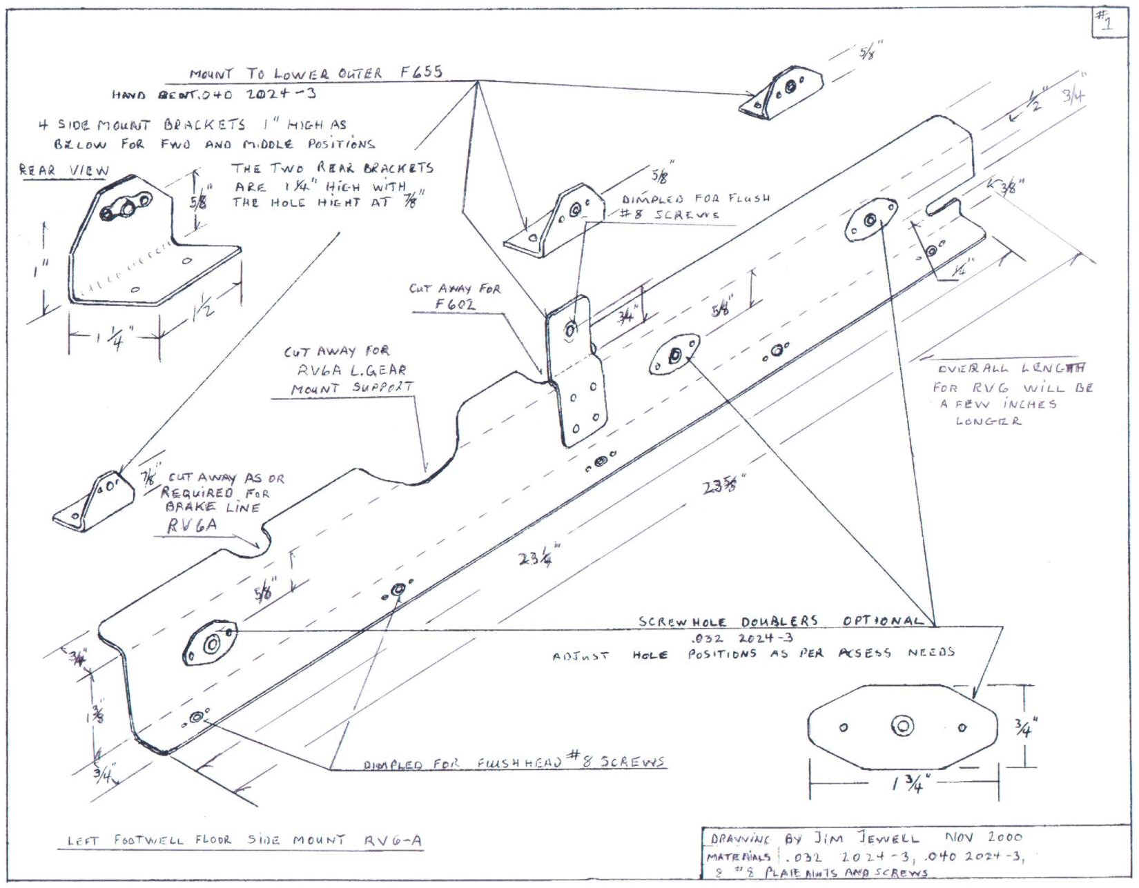
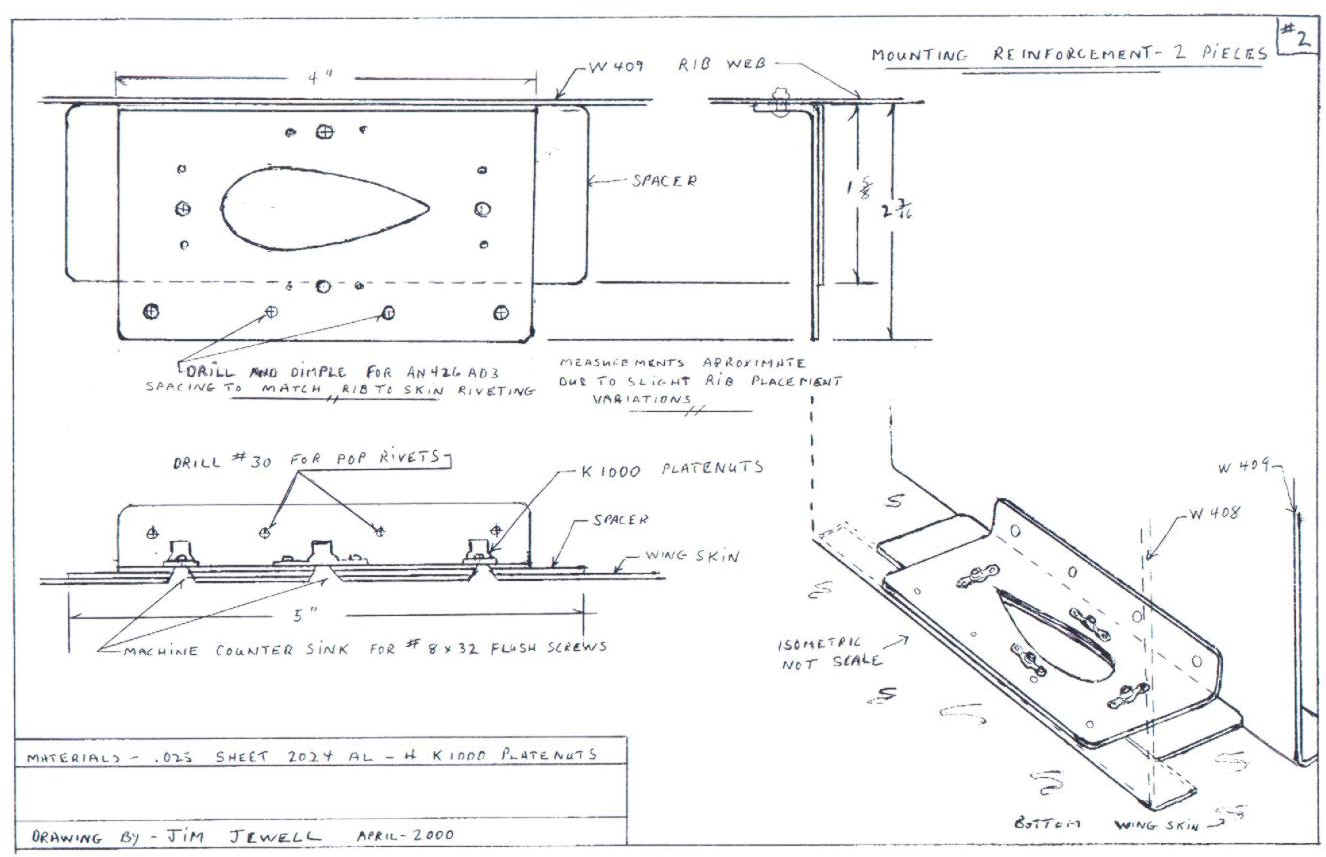
I'm not far enough along in my project to appreciate this modification but it seems interesting. There have been comments in the past from builders who have had problems with "smoking rivets" on the belly of the fuselage. The name "Smoking Rivets" comes from the mess that is made when the belly rivets loosen up a little and the vibration and rubbing action creates a dust (aluminum dust probably) that covers the area around the loose rivets. Jim drew up these plans to strengthen and further support the cockpit floor area and, hopefully, decrease the chances of this problem. Additionally, this should subdue any vibration noises and pulses that the pilot and passengers feel through their feet.
The concept of aluminum floor boards come from another builder. In
the past I have seen a variety of solutions to fitting flooring under the
rudder/brake pedals. Many of them include various kinds of insulation,
wood, composites material and carpets of some type. Many of these
materials collectively added at least a few if not several pounds to the
forward C/G Some where glued in place, some wedged, wired, screwed,
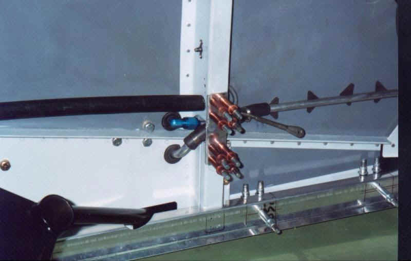
etc. Firstly, I have added a series of staggered rivets to the
existing floor angles to deal with the reported "smoking
rivets". My first problem was to establish some sort of area to
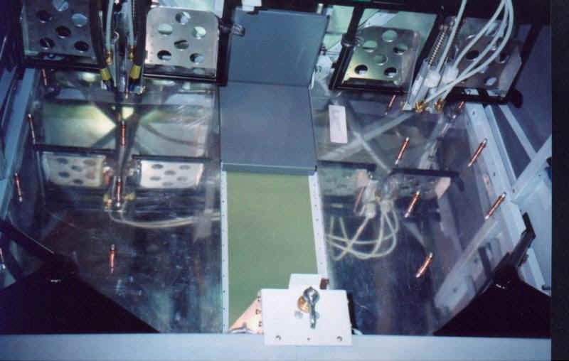
attach the outer edges of the flooring( drawing #1). After that the need
to attach the flooring to the floor ribs needed attention. Then the front
of the floor area looked unfinished and could trap small things
dropped into the floor area (drawing # 3) then the dimensions and fitting
of the floor sheeting could be established (Drawing # 2). I intend
to apply some light weight and fire proof insulation to the bottom of the
floor sheeting thus leaving the actual floor and floor angles free to
breathe thereby reducing the chance of corrosion.
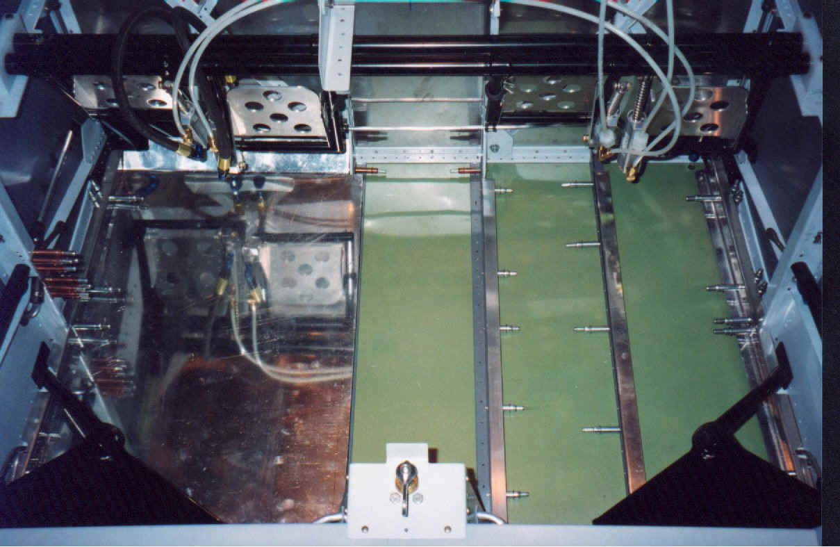
The floor strength with the screws in place is improved greatly. It is
also assumed by me that some amount of noise and heat transfer reduction
should be realized."
"The addition of the floors does change how the battery box etc. is mounted. I think the change should make it easier to bolt the battery mount to the frame work, that is the reason for the 10/32 platenuts in the center angles. The light weight recombinant batteries will live quite well with just a post top shield or cover and a secure hold down system. I'm thinking of coating the floor panels with wing a walk type of paint on finish. the wife might prefer some type of light weight carpet with scuff plates under the rudder pedals. I have to admit the carpet idea looks nicer". - Jim Jewell